SCPA075 October 2024 TPLD1201 , TPLD1201-Q1 , TPLD1202 , TPLD1202-Q1 , TPLD801 , TPLD801-Q1
TI Programmable Logic Devices (TPLD) can be used to drive indicator light-emitting diodes (LED), and can be programmed to provide simple or complex LED control in a single package. The application pictured in Figure 1 uses the internal oscillator, counter, and DFF modules included in the TPLD1201 to drive an LED. The counter and DFF divide down the oscillator frequency so that the LED blinks at a frequency detectable by the human eye.
 Figure 1 Blinking LED Schematic
Example Configuration
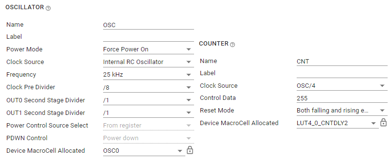
The 25kHz oscillator is given a pre-division of 8, outputting a 3125Hz square wave. The counter module CLK input is sourced from the 25kHz oscillator output further divided by 4, such that the input CLK frequency to the counter becomes 781.25Hz. The counter data is set to 255 (meaning the counter outputs a pulse after 255 rising edges are provided on the CLK input), causing the counter to output a pulse at a frequency of 3Hz. This 3Hz pulse output is fed into a (DFF) with the inverted output option enabled, allowing the DFF to further divide the frequency by half. This 1.5Hz output pulse is then connected to a pin configured to be a push-pull digital output with 2 × drive strength. This pin can be used to drive an LED with a maximum drive strength of 17mA without damaging the device.
 Figure 2 Oscillator and Counter
Configurations
 Figure 3 DFF and Pin
Configurations
Figure 3 DFF and Pin
ConfigurationsDesign Considerations
- Indicator LEDs typically need 1mA to 20mA of drive current to illuminate. The resistive load at the output pins driving the LEDs must be greater than (VCC ÷ IDC)Ω to prevent the absolute maximum current output ratings being violated. These current ratings depend on the type of output structure the output pins are programmed for (TPLD1201 pins can be programmed as push-pull or open-drain outputs, with drive strength gains of 1 × or 2 ×). Choose LEDs with forward currents that do not exceed IDC for the chosen output pin configuration at the appropriate VCC.
- Different LED colors require different forward voltages
| Red | Orange | Yellow | Green | Blue | White |
|---|---|---|---|---|---|
| 1.8V | 2.0V | 2.2V | 3.5V | 3.6V | 4.0V |
- Series resistors are used to
limit the current through the LEDs and can be estimated with Equation 1:
Equation 1. - If the output pins of the device are configured as open-drain, NMOS, or PMOS, choose appropriate pulldown or pullup resistors of 10kΩ in Interconnect Studio (ICS) to avoid floating signals on the outputs.
- The output voltage of a logic gate (VOH or VOL) is specified at a given test current only
- [FAQ] How do I determine the output voltage or output current of a CMOS logic device?
- Need additional assistance? Ask our engineers a question on the TI E2E™ logic support forum