SLAAEH2A December 2023 – June 2024 TAA5212 , TAC5111 , TAC5112 , TAC5211 , TAC5212 , TAD5112 , TAD5212
3.3.1 Default Mode (Main Fs - Higher rate)
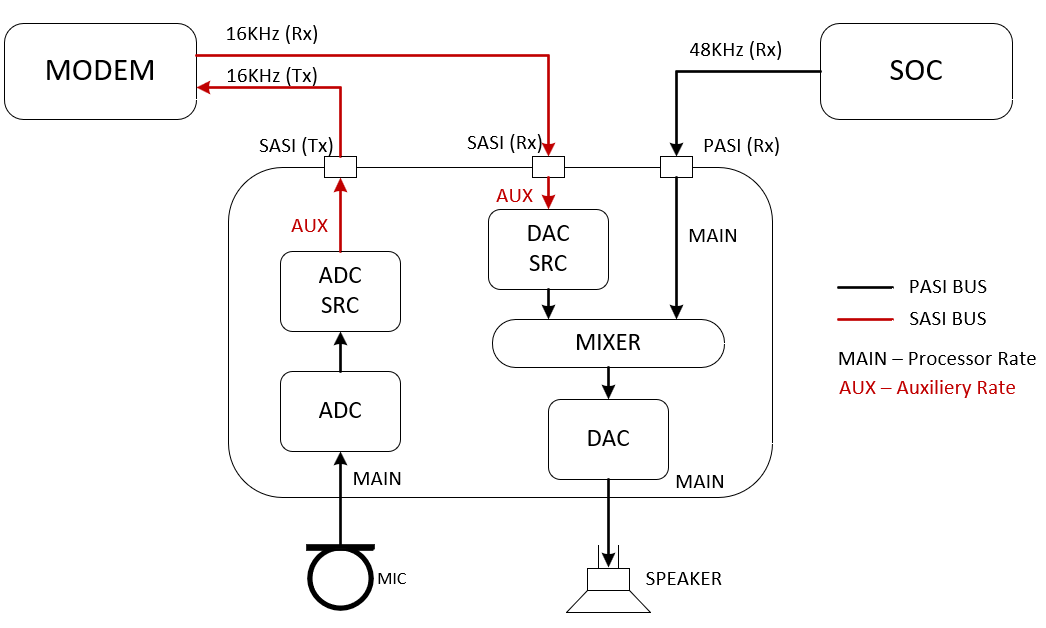
Figure 3-3 is a block diagram for this use case with PASI and SASI mapping. PASI is running at 48 KHz and SASI is at 16 KHz. In this use case the analog (MIC) input sampled at main Fs and down-sampled with SRC to a lower rate for SASI TX. The PASI TX is available as well at 48 KHz. On the DAC side, SASI RX data can mix with PASI RX data prior to DAC output (Speaker).
 Figure 3-3 Default Mode Diagram
The Audio Precision APx555 configurations for PASI and SASI are shown below. In this test case mixer coefficients are kept to its default (full-sacle) and the input levels are adjusted as not to exceed the maximum allowed level for example -6dBrG instead of 0dBrG.
|
PASI APx555: Generator: Analog Output (MIC)∶ 1KHz Sine, -6 dBrG (0dBrG = 2Vrms) Analyzer: Input 1∶ Digital audio for PASI Tx with Fs = 48 KHz, TDM, 32 bit depth Input 2∶ Analog input from DAC output (Speaker) SASI APx555: Generator: Digital Output∶ 750Hz Sine, -6 dBFS Analyzer: Input 1∶ Digital audio for SASI Tx with Fs = 16 KHz, TDM, 32 bit depth |
##### PASI higher rate, default SRC Mode Testing ######
# Target Mode, TDM, 32-bit
# Primary and Secondary ASI, multiple of 48KHz Sampling
# GPIO2=Secondary FSYNC, GPIO1=Secondary BCLK, GPI1=Secondary DIN, GPO1=Secondary DOUT for 4x4
#
w a0 00 00        # Set page 0
w a0 01 01        # Software Reset
w a0 02 09        # Wake up with AVDD > 2v and all VDDIO level
w a0 0a 10        # GPIO1 as input
w a0 0b 10        # GPIO2 as input
w a0 0d 02        # GPI1 as input
w a0 0c 71        # GPO1 as Secondary DOUT
w a0 11 a2        # Enable PASI DIN and Set GPI2A as Secondary FSYNC and GPIO1 as Secondary BCLK
w a0 12 60        # Set GPI1A as Secondary DIN
w a0 18 00        # Enable both Primary and Secondary ASI as independent
w a0 34 40        # PASI BCLK is the input clock source
w a0 19 00        # 1 data input and 1 data output for PASI and SASI
w a0 1a 30        # PASI TDM, 32 bit format
w a0 1e 20        # PASI DOUT Ch1 on TDM slot 0
w a0 1f 21        # PASI DOUT Ch2 on TDM slot 1
w a0 28 20        # PASI DIN Ch1 on TDM slot 0
w a0 29 21        # PASI DIN Ch2 on TDM slot 1
w a0 00 03        # Set page 3
w a0 1a 30        # SASI TDM, 32 bit format
w a0 1e 20        # SASI DOUT Ch1 on TDM slot 0
w a0 1f 21        # SASI DOUT Ch2 on TDM slot 1
w a0 28 20        # SASI DIN Ch1 on TDM slot 0
w a0 29 21        # SASI DIN Ch2 on TDM slot 1
w a0 00 01        # Set page 1
w a0 17 00        # Default SR-Converter with auto-detect
w a0 18 00        # auto m:n ratio
w a0 2c 80        # Enable DAC ASI Mixer
w a0 00 00        # Set page 0
w a0 50 00        # ADC Ch1 diff input, 5KOhm, 2Vrms ac-coupled, audio band
w a0 55 00        # ADC Ch2 diff input, 5KOhm, 2Vrms ac-coupled, audio band
w a0 64 20        # Configure OUT1P/M as differential from DAC1
w a0 65 20        # Configure OUT1P LINEOUT 0dB audio band
w a0 66 20        # Configure OUT1M LINEOUT 0dB 2Vrms Differential
w a0 6b 20        # Configure OUT2P/M as differential from DAC2
w a0 6c 20        # Configure OUT2P LINEOUT 0dB audio band
w a0 6d 20        # Configure OUT2M LINEOUT 0dB 2Vrms Differential
w a0 76 cc        # Enable Input and Output Ch1 and Ch2
w a0 78 e0        # Power up ADC, DAC and MICBIAS
Test Results
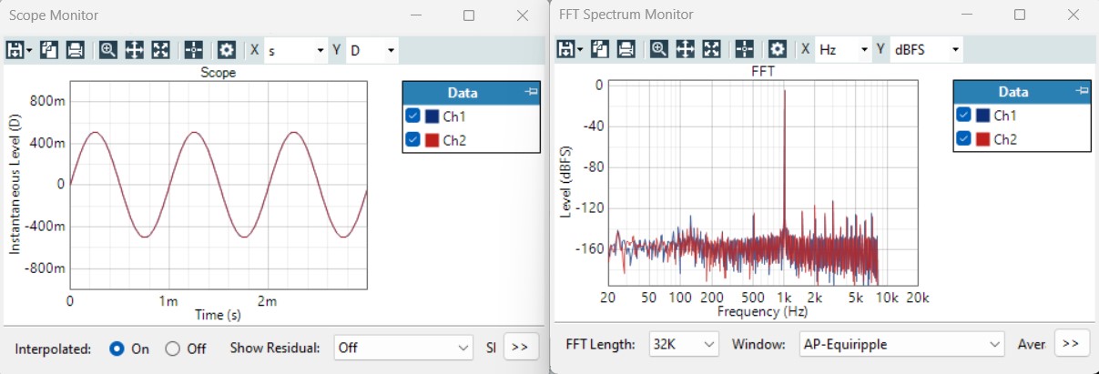
The following plots show the results of the ADC output at SASI TX after SRC. The frequency response (FFT) ends at 8 KHz (Fs/2 of SASI rate of 16 KHz) as expected.
On Speaker output, the tone captured is the SASI RX tone of 750 Hz after SRC. PASI RX tone is muted in this case.
Figure 3-4 shows SASI TX 1 KHz tone from MIC input after SRC.
 Figure 3-4 SASI ADC Output
Figure 3-5 shows 750 Hz tone from SASI RX after SRC, PASI RX tone is muted.
 Figure 3-5 Speaker Output