SLAAEH6 September 2024 TAA5212 , TAA5412-Q1 , TAC5111 , TAC5111-Q1 , TAC5112 , TAC5211 , TAC5212 , TAC5212-Q1 , TAC5311-Q1 , TAC5312-Q1 , TAC5411-Q1 , TAC5412-Q1 , TAD5112 , TAD5112-Q1 , TAD5212 , TAD5212-Q1
- 1
- Abstract
- Trademarks
- 1Introduction
- 2Infinite Impulse Response Filters
-
3TAC5x1x and TAC5x1x-Q1 Digital Biquad
Filters
- 3.1 Filter Design using PurePath™ Console
- 3.2 Generating Coefficients N0, N1, N2, D1, D2 using a Digital Filter Design Package
- 3.3 Avoiding Overflow Conditions
- 3.4 Biquad Filter Allocation on Recording Channel
- 3.5 Biquad Filter Allocation on Playback Channel
- 3.6 Biquad Filter Programming Example on the TAC5x1x
- 4Typical Audio Applications of Biquad Filters
- 5Summary
- 6References
3.1 Filter Design using PurePath™ Console
To facilitate the use of the biquad filters, the PurePath™ Console includes a graphical filter design section that plots the magnitude, phase, and group delay versus frequency. This filter design also generates the coefficients through several different filter design techniques filters.
Table 3-1 lists the different types of filters supported in the PurePath™ Console. Through bi-linear transformation (BLT), the analog filter equations shown in the table can be converted from the S-domain to the digital Z-domain. In these filters, each pole of the filter provides a –6dB per octave or –10dB per decade slope in the frequency response. Each zero of the filter provides a +6dB per octave or +10dB per decade slope in the frequency response.
In the transfer functions shown in the Table 3-1, ωc corresponds to the center/corner frequency of the filter, and Q refers to the quality factor of the filter.
| Filter Type | Filter Transfer FunctioN (S-domain) | Filter Description |
|---|---|---|
| Band Pass |
| Band-Pass filter at the specified center frequency and passband width (filter bandwidth) |
| Bass Shelf |
| Specified gain applied at the low frequency up to the specified cutoff frequency |
| Equalizer (Bandwidth) |
| Band-pass filters at the specified center frequency and passband width, with the specified gain |
| Equalizer (Q Factor) | Band-pass filter at the specified center frequency and quality factor, with the specified gain. The quality factor is the center frequency divided by the passband width. | |
| Gain |
| All pass filter at the specified gain |
| High-Pass Butterworth 1 |
| First-order high-pass filter with specified gain, specified cutoff frequency, maximally flat passband and stopband response. Stopband frequency response has a –10dB / decade slope. |
| High-Pass Butterworth 2 | Second-order high-pass filter with specified gain, specified cutoff frequency, maximally flat passband and stopband response. Stopband frequency response has a –20dB / decade. | |
| High-Pass Bessel 2 |
| Second-order high-pass filter with specified gain, specified cutoff frequency, maximally flat phase and constant group delay across passband. |
| High-Pass Linkwitz Riley 2 |
| Second-order high-pass filter composed of a Butterworth filter with –3dB at the cutoff frequency. When cascading a low-pass and high-pass Linkwitz Riley filters, the overall gain at the crossover frequency is 0dB. |
| High-Pass Variable Q 2 |
| Second-order high-pass filter at the specified center frequency, gain, and quality factor. The quality factor is the center frequency divided by the passband width. |
| High-Pass Chebyshev |
| High-pass filter with equiripple in the passband with maximally flat response in stopband |
| Low-Pass Butterworth 1 |
| First-order low-pass filter with specified gain, specified cutoff frequency, maximally flat passband and stopband response. Stopband frequency response has a –10dB / decade slope. |
| Low-Pass Butterworth 2 | Second-order low-pass filter with specified gain, specified cutoff frequency, maximally flat passband and stopband response. Stopband frequency response has a –20dB / decade. | |
| Low-Pass Bessel 2 |
| Second-order low-pass filter with specified gain, specified cutoff frequency, maximally flat group delay across passband |
| Low-Pass Linkwitz Riley 2 |
| Second-order low-pass filter composed of a Butterworth filter with –3dB at the cutoff frequency. When cascading a low-pass and high-pass Linkwitz Riley filters, the overall gain at the crossover frequency is 0dB. |
| Low-Pass Variable Q 2 |
| Second-order low-pass filter at the specified center frequency, gain and quality factor. The quality factor is the center frequency divided by the passband width. |
| Low-Pass Chebyshev |
| Low-pass filter with equiripple in the passband with maximally flat response in stopband |
| Notch |
| Band stop filter at the specified center frequency and stopband width (filter bandwidth) |
| Phase Shift |
| All pass filter with 180 degree phase shift at the specified center frequency through the width given by the bandwidth |
| Treble Shelf |
| Specified gain applied at the high frequencies past the specified cutoff frequency |
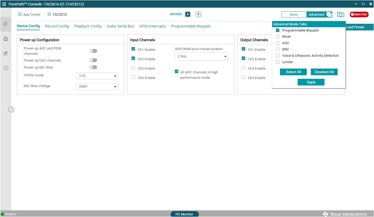
In PurePath™ Console, the programmable biquad filter configuration is available in the "Advanced" tab of of user interface. Figure 3-2 shows the option to enable this feature.

Figure 3-2 Enabling Biquad Filter Programmability in PurePath™ Console