SLAAEK6 June 2024 ULC1001 , ULC1001-Q1
3.4.3 Thin Film
As the interface between the Lens Cover and Housing, the flexible polyamide is chosen. The reasons why choosing polyamide film as the interface include the following:
- Very flexible with a flexural modulus of 2.5GPa to reduce damping.
- High tensile strength of up to 340MPa.
- Excellent thermal stability, normal use in -100°C to 260 °C.
- Different thicknesses are available with 10um – 1000um.
- Low cost and easy to pattern.
- Other materials (Al, SS, film, nylon, plastic, etc) can be potentially used.
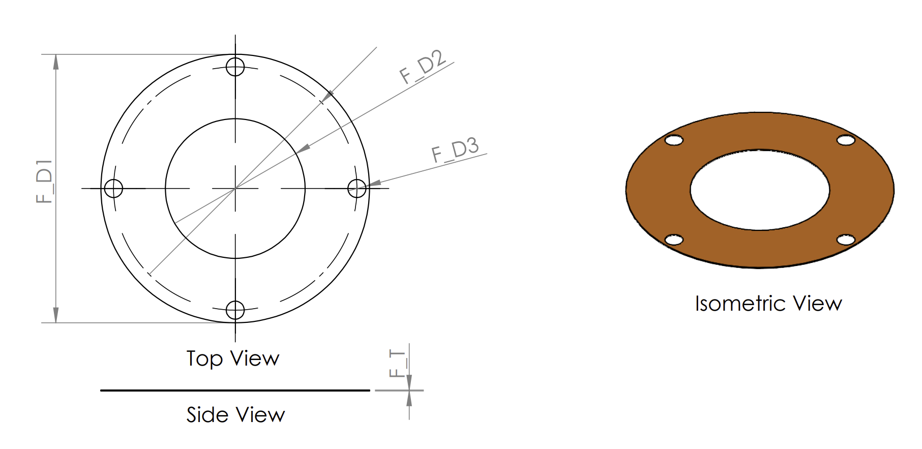
Figure 3-8 shows the top view, side view and isometric view of the thin film in the application. The pattern is so that the inner diameter (F_D2) is identical to the inner diameter of the piezo transducer. Four small holes are designed for screwing purpose.
 Figure 3-8 Thin Film: Top View, Side View and
Isometric View