SLAAEK6 June   2024 ULC1001 , ULC1001-Q1


  1.   1
  2.   Abstract
  3.   Trademarks
  4. 1Acronyms
  5. 2Introduction
  6. 3Design Principles
    1. 3.1 Critical Acceleration
    2. 3.2 LCS Architecture
    3. 3.3 Design Procedure
    4. 3.4 Design of Components
      1. 3.4.1 Lens
      2. 3.4.2 Transducer
      3. 3.4.3 Thin Film
      4. 3.4.4 Glue Fixture
      5. 3.4.5 Housing
        1. 3.4.5.1 Housing Cap
        2. 3.4.5.2 Flexible Seal
        3. 3.4.5.3 Housing Base
  7. 4Fabrication Principles
    1. 4.1 Lens
    2. 4.2 Transducer
    3. 4.3 Thin Film
    4. 4.4 Glue Fixture
    5. 4.5 Housing
  8. 5Assembly Principles
    1. 5.1 Step 1: Gluing Components into Lens Cover
    2. 5.2 Step 2: Soldering of Lens Cover with Wires
    3. 5.3 Step 3: Assemble Lens Cover into Housing
  9. 6Example: CAD Drawings for Aperture = 15mm
  10. 7Resources

Housing Cap

The cap contains a trench to hold the seal in place and provides the waterproof. The cap can be designed to have threads and screw onto the housing or a fixed cap and housing assembly can be designed. Figure 3-10 shows the top view and section view of the housing cap. A slope is recommended on the opening of the cap to increase the field of view and also the waterdroplet can roll off along the slope.

Material: The cap material must be strong and durable for the application. TI has used Delrin Acetal Homopolymer Black for prototyping.
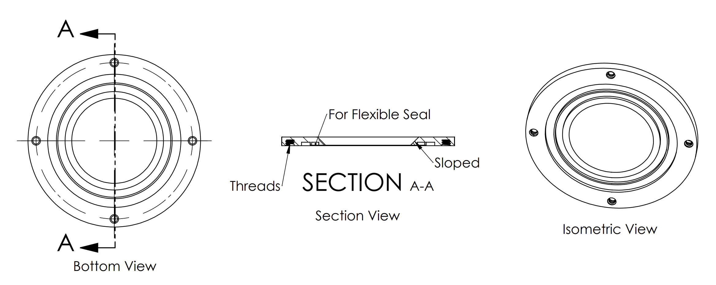
 Housing Cap: Top View and
                    Section View Figure 3-10 Housing Cap: Top View and Section View