SLAAEK6 June   2024 ULC1001 , ULC1001-Q1


  1.   1
  2.   Abstract
  3.   Trademarks
  4. 1Acronyms
  5. 2Introduction
  6. 3Design Principles
    1. 3.1 Critical Acceleration
    2. 3.2 LCS Architecture
    3. 3.3 Design Procedure
    4. 3.4 Design of Components
      1. 3.4.1 Lens
      2. 3.4.2 Transducer
      3. 3.4.3 Thin Film
      4. 3.4.4 Glue Fixture
      5. 3.4.5 Housing
        1. 3.4.5.1 Housing Cap
        2. 3.4.5.2 Flexible Seal
        3. 3.4.5.3 Housing Base
  7. 4Fabrication Principles
    1. 4.1 Lens
    2. 4.2 Transducer
    3. 4.3 Thin Film
    4. 4.4 Glue Fixture
    5. 4.5 Housing
  8. 5Assembly Principles
    1. 5.1 Step 1: Gluing Components into Lens Cover
    2. 5.2 Step 2: Soldering of Lens Cover with Wires
    3. 5.3 Step 3: Assemble Lens Cover into Housing
  9. 6Example: CAD Drawings for Aperture = 15mm
  10. 7Resources

Flexible Seal

The seal between the cap and the thin film maintains a watertight proof as the lens cover vibrates to expel contaminants. Figure 3-11 illustrates the top view, side view, and isometric view of the seal for housing after hardening.

Material: The recommended seal material is silicone that is soft enough to induce minimal damping during ULC vibration and that can also avoid cracking over weather temperature cycles during the product life cycle. This exhibits excellent resistance to heat, compression set, boiling water, and has excellent low-temperature flexibility.
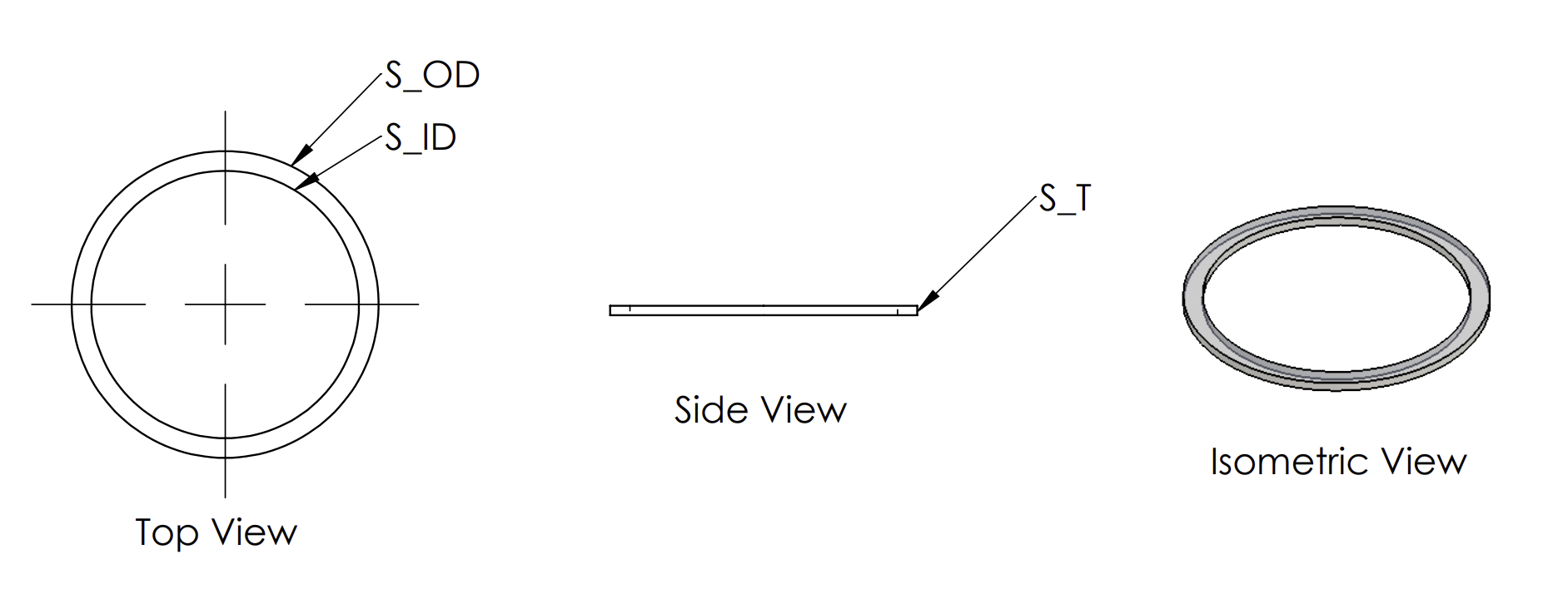
 Seal: Top View, Side View and Isometric View after HardeningFigure 3-11 Seal: Top View, Side View and Isometric View after Hardening