SLAAEK6 June 2024 ULC1001 , ULC1001-Q1
3.4.1 Lens
In the camera lens cover system, the lens is a transparent piece of material that defines the physical barrier between the environment and the camera lens system. The lens vibrates in the ultrasonic frequency range with enough energy to remove contaminants (for example, rain droplets, snowflakes, mud, or dust) that can be on the lens.
For a thin flat circular lens, the resonant frequency can be estimated by the following equation:
Where is the natural frequency for the ith nodal diameter and jth nodal circle, Hz.
is the eigenvalue for the ith nodal diameter and jth nodal circle (unitless).
is the radius of the lens, m.
is modulus of elasticity for the cover glass material, N/m2.
is the thickness of the cover glass, m.
is the mass per unit area of the cover glass material, kg/m2.
is Poisson’s ratio for the cover glass material (unitless).
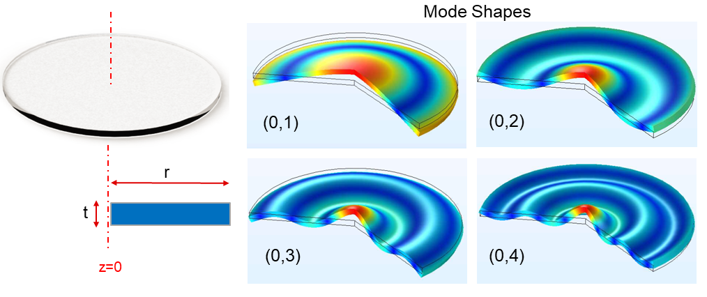
Figure 3-5 shows the mode shapes of the lens only. In the design, modes (0 1) and (0 2) are utilized for cleaning with fewer nodal points (little displacement in blue color). Also, the modes have lower resonant frequencies and therefore require smaller critical acceleration.
 Figure 3-5 Mode Shapes of Lens Only
Material: A desirable lens material must have the following properties in the application:
- High bending strength. Capable of handling high stress during vibration for cleaning without cracking or breaking.
- High light transmittance for the wavelength of light used by the camera imaging system. For automotive, the wavelength can be infrared (IR) or visible.
The optional materials include N-BK7®, fused silica glass, Gorilla® Glass 3, polycarbonate, silicon, and so forth, and the key mechanical properties of the materials are listed in Table 3-1. TI recommends CDGM HK9LGT® for general cleaning purposes considering the favorable material properties, mature fabrication feasibility, and relatively low cost. However, a material with comparable properties can also be used.
| Manufacturer | Material | Young’s Modulus (GPa) | Density (kg/m3) | Poisson’s Ratio |
|---|---|---|---|---|
| Tosoh | Fused Silica Glass N | 74 | 2200 | 0.17 |
| Corning® | Gorilla® Glass 3 | 69.3 | 2390 | 0.22 |
| Corning | Gorilla® Glass 5 | 76.7 | 2430 | 0.21 |
| Covestro | Polycarbonate | 2.34 | 1200 | 0.38 |
| Schott | NBK7® | 82 | 2510 | 0.206 |
| CDGM | HK9LGT® | 79.2 | 2520 | 0.211 |