SLAAEM1 June 2024 MSPM0C1104 , MSPM0C1104 , MSPM0L1105 , MSPM0L1105
4.3 Timer Interrupt
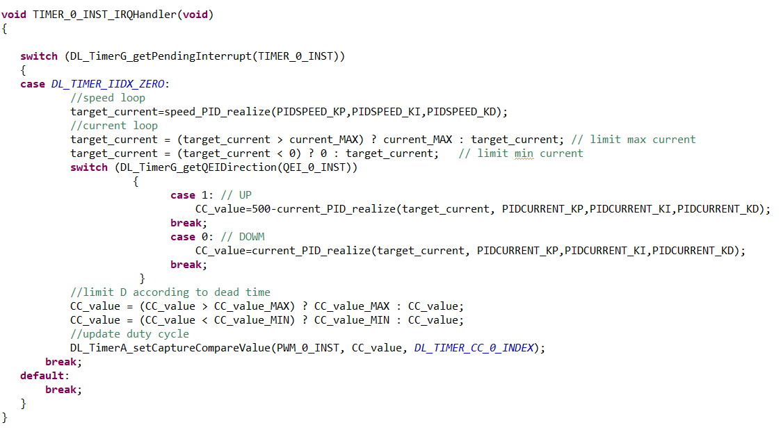
The timer is configured in countdown mode, triggering an interrupt when it reaches zero. The counting period is set to 50ms, meaning the duty cycle is updated every 50ms. Within this interrupt function, the current reference value is calculated first using the speed loop controller, and current is then clamped. Subsequently, the duty cycle is determined using the current loop controller, meanwhile considering the dead-time. Finally, the duty cycle information is updated based on the actual direction of the motor.
 Figure 4-4 Timer Interrupt