SLAAEM1 June 2024 MSPM0C1104 , MSPM0C1104 , MSPM0L1105 , MSPM0L1105
2 System Architecture Introduction
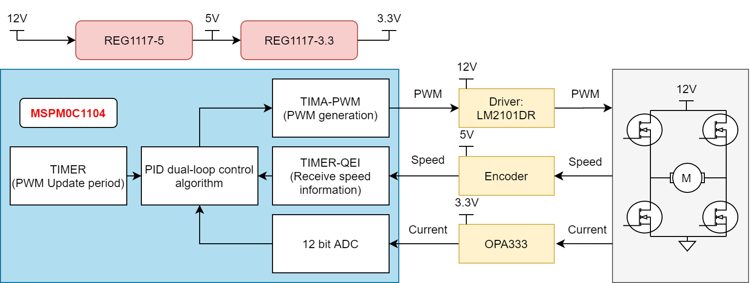
Figure 2-1 shows the system block diagram for the motor driver solution. In addition to the MSPM0C1104 and power loop, the system primarily consists of three components: the power supply circuit, the driver circuit, and the sampling circuit.
 Figure 2-1 System Block Diagram
The sampling circuit collects the motor's current and velocity information through an encoder and operational amplifier, and then sends them to the MCU. The MCU computes the duty cycle through a PID closed-loop and generates PWM signals based on real-time velocity and current information. The MOSFET driver circuit converts the PWM signal generated by the MCU into a driving signal to control the MOSFET switch. The power supply circuit provides proper power rails to all the components in the system, such as MCU, encoder, driver, OPA and so on. A detailed description of the hardware circuitry and a portion of the software control code will be provided as follows.