SLAAEM1 June 2024 MSPM0C1104 , MSPM0C1104 , MSPM0L1105 , MSPM0L1105
3.3 Sampling Circuit
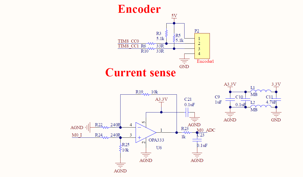
The sampling circuit is mainly divided into speed sampling and current sampling. Speed sampling is realized by an encoder, which can send square signal containing speed information to the MCU. As for current feedback circuit, the current is converted to voltage through the sensing resistor. Then through the amplifier circuit, the voltage is amplified to within the sampling range of the analog-to-digital converter (ADC).
 Figure 3-4 Sampling Circuit