SLAAEM1 June 2024 MSPM0C1104 , MSPM0C1104 , MSPM0C1105 , MSPM0C1105 , MSPM0C1106 , MSPM0C1106 , MSPM0H3216 , MSPM0H3216 , MSPM0L1105 , MSPM0L1105
5 Evaluation
To evaluate the solution, the following hardware elements are required:
- A computer with Windows® 7 or later, and .NET Framework 4.5
- 12V DC power supply
- XDS110 debug probe
- Connector for driver board and debugger communication
- USB for PC and driver board communication
- Brushed DC motor with encoder.
(ATK-JGB37-520E, the spec is as shown in Table 5-1)Table 5-1 JGB37-520E Motor Parameters
Item Value Rated voltage DC 12V Current 0.2-0.5A Idle speed 333RPM (peak value) Gear Ratio 30:1 - Motor
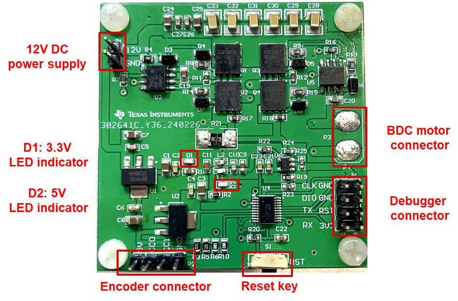
control board is shown as Figure 5-1.
 Figure 5-1 Motor Control
Board
 - Example code is shown in Section 4.
Once the necessary hardware and code are prepared, the hardware connection can be made according to the above description. After that, the sample code can be burned into the chip via the Code Composer Studio™ (CCS) software, and the evaluation of the solution can be carried out. The paper provides an economically flexible driving solution for brushed DC motors based on TI's MSPM0C1104, significantly reducing system costs while ensuring overall performance. Customers can flexibly develop based on this solution according to their actual needs.