SLAAEP4 December 2024 BQ79616 , MSPM0G3507
3.2 Software Function and Flow Diagram
MSPM0 communicates with BQ79616 base device through universal asynchronous receiver/transmitter (UART), and BQ79616 stack devices communicate with BQ79616 base device through daisy chain.
There are two types of communication method that BQ79616 base device can communicates with MSPM0, one is PING mode and the other is UART mode. In PING mode, BQ79616 devices switch the working mode between WAKE, SLEEPtoACTIVE, SHUTDOWN, HW_RESET, according to the low-level duration time sent by MSPM0 UART Tx pin. And in UART mode, MSPM0 and BQ79616 communicate in normal UART mode, and MSPM0 configure different functions by changing BQ79616's registers through UART.
MSPM0 can control BQ79616's working mode in PING mode and uses UART to control BQ79616's register and read back BQ79616's data through UART. Functions Auto address, Reverse address, Passive balance, Fault report, and so forth are included in demo code.
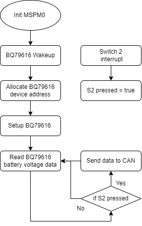
MSPM0 initialize BQ79616, measure cell voltage and send voltage data through CAN to CAN analyzer, software flow diagram is shown in Figure 3-1.
 Figure 3-1 MSPM0 Software Diagram