SLAAEP4 December 2024 BQ79616 , MSPM0G3507
3.3.1 UART and Daisy Chain
In a BQ79616 daisy chain communication structure, MSPM0 communicates directly with the BQ79616 base device through UART, and BA79616 base device communicates with BQ79616 stack devices through daisy chain.
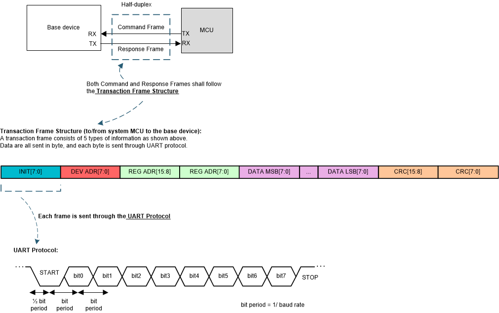
The data structure transmitted between MSPM0 and BQ79616 is shown in Figure 3-2, each byte is transmitted in standard UART protocol, and UART baud rate is 1MHz. The data structure is defined below:
- Frame initialization (INIT, 1 byte)
- Device address (DEV ADR, 1 byte)
- Register address (REG ADR, 2 bytes)
- Data (DATA, various byte length)
- Cyclic redundancy check (CRC, 2 bytes)
 Figure 3-2 UART Communication to Host
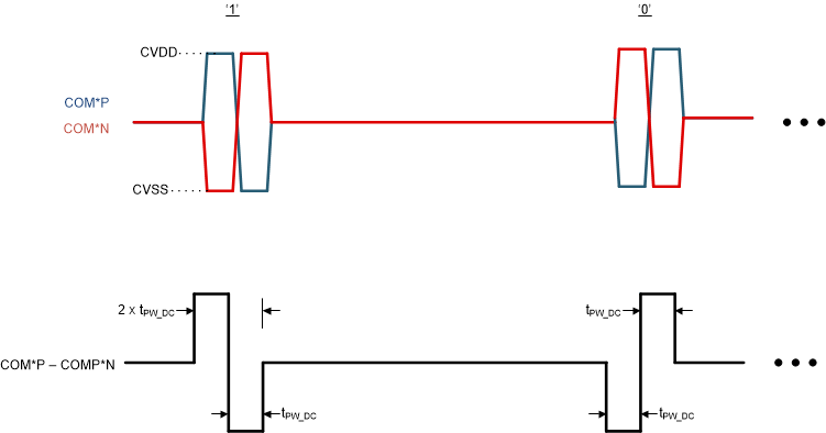
DIR0_ADDR and DIR1_ADDR are two 6 bits device address registers, these two registers are used to recognize different BQ79616 devices connected through daisy chain. During the system initialization, MSPM0 executes BQ79616 auto address function, the base device's address is 0, the stack device's addresses starts from 1 and increases by one, the total BQ79616 quantity can be up to 64 pieces. To improve the communication robustness, the daisy chain transmits bit through COMH COML differential voltage signal. The voltage level is defined in Figure 3-3.
 Figure 3-3 Daisy Chain Bit Definition
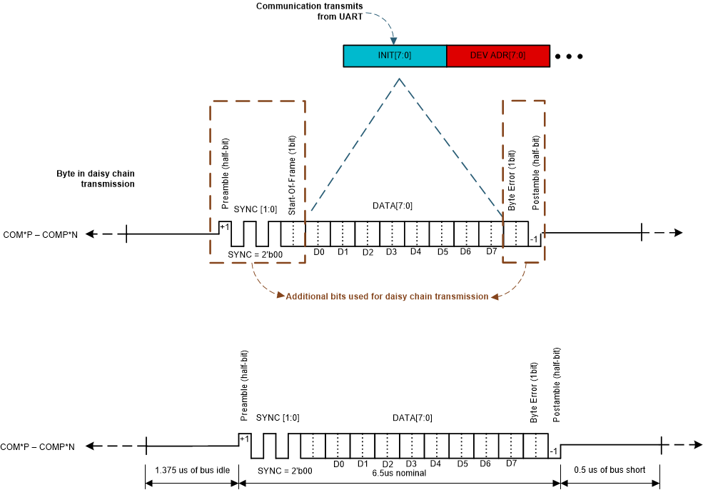
The daisy chain uses 13-bit binary to transmit one byte of data, and the content corresponds one-to-one with the UART byte sent or received by the base device. The data structure is defined in Figure 3-4.
- Preamble (half bit)
- SYNC [1:0]
- Start-Of-Frame (1 bit)
- Data [7:0]
- Byte Error BERR (1 bit)
- Post amble (half bit)
 Figure 3-4 Daisy Chain Byte Definition
Based on UART and daisy chain communication protocol, communication between MSPM0 and BQ79616 stack devices can support the function shown in Table 3-2.
| Command | Description |
|---|---|
| Single device read | To read register from a single device (base or stack) |
| Single device write | To write register to a single device (base or stack) |
| Stack read | To read register from the stack devices only. The device must be configured as a stack device with COMM_CTRL[STACK_DEV] = 1 to respond to Stack Read commands. |
| Stack write | To write register for only the stack devices. The device must be configured as a stack device with COMM_CTRL[STACK_DEV] = 1 to respond to Stack Write commands. |
| Broadcast read | To read register for all of the devices in the daisy chain, including the base device. |
| Broadcast write | To write register for all of the devices in the daisy chain, including the base device. |
| Broadcast write reverse direction | To send a broadcast write in the reverse direction set by CONTROL1[DIR_SEL] bit. This command is intended to be used for switching the communication direction with the RING interface. |