SLAAEP4 December 2024 BQ79616 , MSPM0G3507
1 Introduction
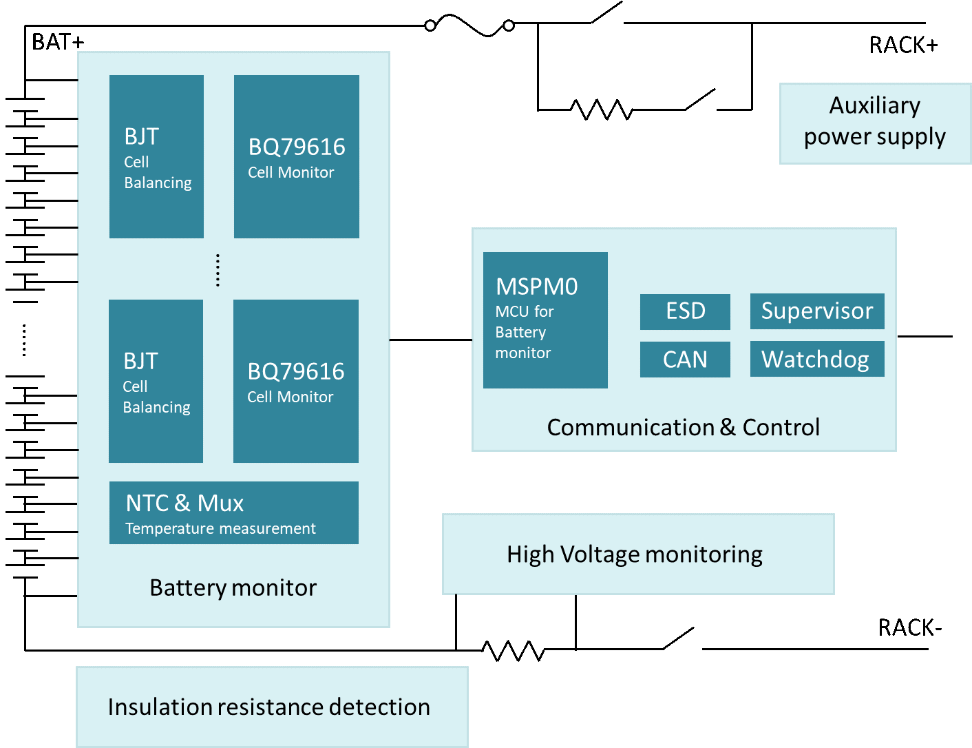
Energy storage has been widely used electric vehicles, power grid, and renewable energy. BMS is the control unit that manages cells in the battery pack. Generally, BMS consists of four modules: power, AFE, communication, control, and monitoring, as shown in Figure 1-1. The auxiliary power component draws power from the battery pack to other parts of the BMS. AFE measures, balances and protects the integrated battery cells at the front end. The communication and control module obtain the measurement data of the AFE for calculation and control and send data to host PC.
This document uses BQ79616 EVM and LP-MSPM0G3507 to build a sample system, providing a design reference for the interaction between AFE and MCU in BMS application. Based on the demo code in MSPM0 SDK, the functions include BQ79616 initialization, BQ79616 data reading and sending data to the CAN bus.
 Figure 1-1 BMS System Block
Diagram