SLAU874 October 2022 TPA3223
-
TPA3223 Evaluation Module
- Trademarks
- 1.1 Quick Start (BTL MODE)
- 1.2 Setup By Mode
- 1.3 Hardware Configuration
- 1.4 EVM Design Documents
- Trademarks
- 1Quick Start (BTL MODE)
- 2Setup By Mode
- 3Hardware Configuration
- 4EVM Design Documents
1.3.3.1 Connections and Board Configuration
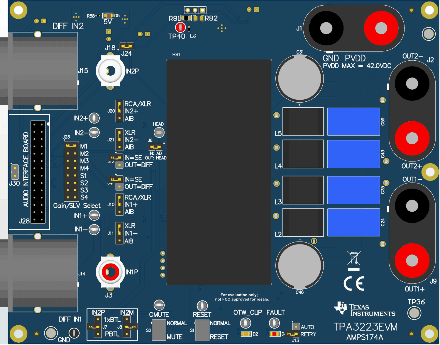
Figure 2-16 illustrates the connectors and jumpers on the EVM.
 Figure 2-16 EVM Board
With Connectors and Jumpers
Figure 2-16 EVM Board
With Connectors and JumpersUse the following steps when connecting and configuring the board:
- Ensure the power supply is OFF. Connect power supply positive terminal to J1 PVDD (red) and negative terminal to J1 GND (black).
- Connect one speaker, power resistor load (3–8 Ω) to TPA3223EVM positive output terminal (J9 OUT1+ (red)) and other side of speaker, power resistor to TPA3223EVM negative output terminal (J9 OUT1– (black)).
- Use a short banana cable to connect J2 OUT2+ to J9 OUT1+ and a second short banana cable to connect J2 OUT2– to J9 OUT1–. This connection forms the parallel connection of both OUTx+ to the one side of the speaker and parallel connection of both OUTx– to the other side of the speaker.
- Check to make sure that the power supply is connected to J1 only and the speaker is connected to J9 or J2 only, as the colors are the same.
- Input Configuration:
- Differential Inputs: connect one differential XLR audio input to DIFF IN1 (J14). Install jumpers J10, J11, J20, and J21 to position 1:2, which is labeled as RCA or XLR. Jumpers J4 and J12 must be uninstalled for DIFF input.
- Single-Ended Inputs: connect one single-ended RCA audio input to IN1P (J3). Install jumpers J10, J11, J20, and J21 to position 1:2, which is labeled as RCA or XLR. Jumpers J4 and J12 must be installed for SE input.
- Audio Interface Board Input: Install jumpers J10, J11, J20, and J21 to position 2:3, which is labeled as AIB. Jumpers J4 and J12 must be installed for SE input from the AIB or uninstalled for DIFF input from the AIB.
- Ensure that RESET S1 and MUTE S2 are in the lower positions of RESET and MUTE, respectively.
- Check Table 2-11 for all jumper and switch configurations necessary.
Table 2-11 Jumper and Switch
Configurations (PBTL Mode)
| Component | Component Description | Configuration for PBTL |
|---|---|---|
| J23 | Gain/CLKSYNC Select | MSTR(Primary) 20 dB |
| J24 | 5V | IN |
| J4, J12 | Input DIFF/SE Select | OUT = DIFF IN, IN =SE IN |
| J10, J11, J20, J21 | AIB Input Select | Position 1:2 for XLR/RCA, Position 2:3 for AIB |
| J6 | HEAD/AD Mode Select | IN |
| J7, J8 | PBTL/BTL Select | Position 2:3 for PBTL |
| S1 | RESET Control | RESET |
| S2 | MUTE Control | MUTE |
| J13 | Auto Retry | OUT |
| J29 | PVDD-IN | IN |
| J26 | 12V-IN | IN |
| J5 | 5V-IN | IN |
| J27 | 3.3V-IN | IN |
| J17 | OSC Output | No Connection |
| J16 | FREQ_ADJ | Position 3:4 MASTER(Primary) MODE |