SLAU883A March 2024 – June 2024 AMC7908
2.1.2 Jumper Definitions
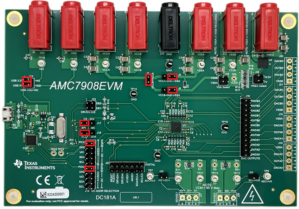
Table 3-1 provides the details of the configurable jumper settings of the AMC7908EVM. Figure 3-2 shows the default jumper connections on the board.
| Designator | Name | Positions |
|---|---|---|
| J2 | VCCA-GND-VSSA | SHORT 1-2 - VCCA is grounded. SHORT 2-3 - VSSA is grounded (default). |
J6 | VCCB = VCCA | SHORT 1-2 - VCCA and VCCB are connected (default). OPEN - VCCA and VCCB are not connected. |
| J9 | VCCB-GND-VSSB | SHORT 1-2 - VCCB is grounded. SHORT 2-3 - VSSB is grounded (default). |
| J13 | USB-VDD-VIO | SHORT 1-2 - VIO is connected to on-board 3.3V (default). SHORT 3-4 - VDD is connected to on-board 5V (default). OPEN - VDD and VIO are powered by external supplies. No other jumper orientation allowed. |
| J17 | CS - SCL | SHORT 1-2 - Uses the FTDI CS pin for SPI mode (default). SHORT 2-3 - Uses the FTDI SCL pin for I2C Mode. OPEN - Open if external communication is used. |
| J18 | SCLK - SDA | SHORT 1-2 - Uses the FTDI SCLK pin for SPI mode (default). SHORT 2-3 - Uses the FTDI SDA pin for I2C Mode. OPEN - Open if external communication is used. |
| J19 | I2C ADDR SELECTION | SHORT 1-2 and 11-12 - SPI configuration (default). SHORT all else - I2C configuration, see Table 3-7 for jumper configurations. OPEN - Open if external communication is used. |
| J23 | DRVEN DIS | SHORT 1-2 - Connects DRVEN0 to FTDI controller. SHORT 3-4 - Connects DRVEN1 to FTDI controller. OPEN - DRVEN0 and DRVEN1 are pulled up to VIO (default). |
| J24 | S0+ = HV0 | SHORT 1-2 - Connects ADCHV0 and SENSE0+ together. OPEN - ADCHV0 and SENSE0+ are separate (default). |
J25 | HV1 = S1+ | SHORT 1-2 - Connects ADCHV1 and SENSE1+ together. OPEN - ADCHV1 and SENSE1+ are separate (default). |
J28 | VNEG Select | SHORT 1-2 - VNEG regulator output is –10.5 V. SHORT 3-4 - VNEG regulator output is –7 V. OPEN - VNEG regulator is not used (default). |
J29 | VSS Select | SHORT 1-2 - VSSB is connected to the VNEG regulator output. SHORT 1-3 - VSSA and VSSB are connected. SHORT 3-4 - VSSA is connected to the VNEG regulator output. OPEN - VSSA and VSSB are powered externally (default). |
 Figure 2-2 AMC7908EVM Default Jumpers