SLLA334B August 2018 – September 2022 ISO1050 , SN6501
3.1 Transformer Driver
Another more compact, less expensive, and more easily designed method is to use a transformer driver. SN6501 provides this solution. SN6501 uses push-pull topology to drive the transformer; it is designed for low-cost, small form-factor, isolated DC-DC converters. The high primary-side can drive current up to 350 mA at 5-V power supply and 150 mA at 3.3 V with a tiny SOT23 package. Small output capacitor is allowed; this benefits from low ripple on rectified output. Those advantages make SN6501 suitable for isolated interface power supply.
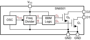
 Figure 3-1 SN6501 Internal Block Diagram
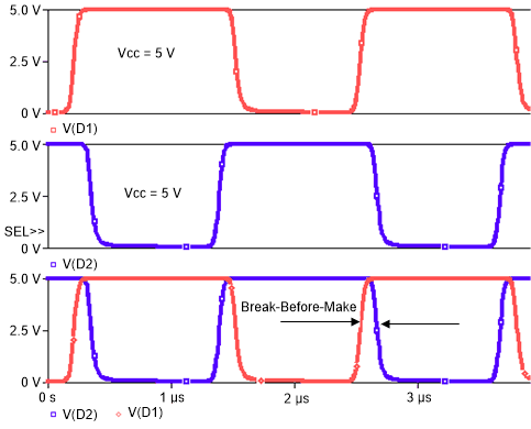
Figure 3-1 shows the SN6501 internal block diagram; it includes an oscillator, a frequency divider, and a break-before-make (BBM) logic. BBM logic outputs two complementary signals, which turn the two output power transistors on and off alternately. Simulation by Pspice model (see Figure 3-2) shows the complementary push-pull waveform with BBM (Vcc is 5 V with no load at the secondary side of transformer).
 Figure 3-2 Switching Waveforms and BBM Waveform by Pspice simulation