SLLA454A April 2019 – August 2024 TUSB211A , TUSB212 , TUSB213 , TUSB214 , TUSB215 , TUSB216 , TUSB217A
- 1
- Abstract
- Trademarks
- 1 Introduction
- 2 USB 2.0 Signal Integrity Challenges
- 3 Choosing to Use a USB 2.0 Redriver
- 4 Redrivers in Automotive
- 5 Redrivers in Enterprise
- 6 Redrivers in Medical
- 7 Re-drivers in Personal Electronics
- 8 Re-drivers in other applications
- 9 Facilitating Easy Use of TUSB211A Using the TUSB211PICO-EVM
- 10Summary
- 11References
- 12Revision History
3 Choosing to Use a USB 2.0 Redriver
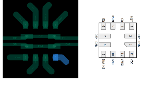
With all those different potential causes for signal degradation of a USB 2,0 signal, the question of whether to use a USB 2.0 redriver and where to use it becomes an important one. Often, designers hesitate under the assumption that adding a redriver can require an extensive rework, and if the redriver does not work, this can require another rework to correct the changes made. Thankfully, a USB 2.0 redriver is actually one of the easier redrivers to implement. USB 2.0 redriver come in a small form factor and flow through trace routing can be used in the board design. Figure 3-1 shows the flow-through design.
 Figure 3-1 Flow-Through Design
Essentially, this flow-through trace routing means that a USB 2.0 redriver does not need to directly integrate a signal through the device as an input to be boosted and then output back onto a trace, but can instead passively monitor the signal as it passes under the redriver. That way, the PCB trace of a board does not need to be extensively reworked to incorporate a USB 2.0 redriver, and if the redriver is not necessary, the redriver can be removed with no worries about whether the trace can be affected or not. Additionally, a USB 2.0 redriver comes in a smaller form-factor, causing it to take up a minimal amount of space in a signal, and is easy to setup, with 1-2 configuration pins at most.