SLLU342 May 2022 TCAN1462-Q1
- Trademarks
- 1Introduction
-
2EVM Setup and Operation
- 2.1
Overview and Basic Operation Settings
- 2.1.1 VCC Power Supply (J2, J3, J9, and TP10)
- 2.1.2 I/O Power Supply VIO (J2, J10, and TP8)
- 2.1.3 Main Supply and I/O Header (J2)
- 2.1.4 TXD Input (J2 or TP6)
- 2.1.5 RXD Output (J2 or TP7)
- 2.1.6 STB or Pin 8 (J1, J2, or TP1)
- 2.1.7 J1 Configuration
- 2.1.8 TP1 Configuration
- 2.1.9 VIO or Pin 5 (J2, J10, or TP8)
- 2.1.10 J10 Configurations
- 2.1.11 J2 Configuration
- 2.1.12 SIC Network Configuration (J7 & J8)
- 2.2 Using CAN Bus Load, Termination, and Protection Configurations
- 2.3 Using Customer Installable I/O Options for Current Limiting, Pullup and Pulldown, Noise Filtering
- 2.1
Overview and Basic Operation Settings
- 3CAN EVM Configuration for TCAN1462-Q1 (Factory Installed)
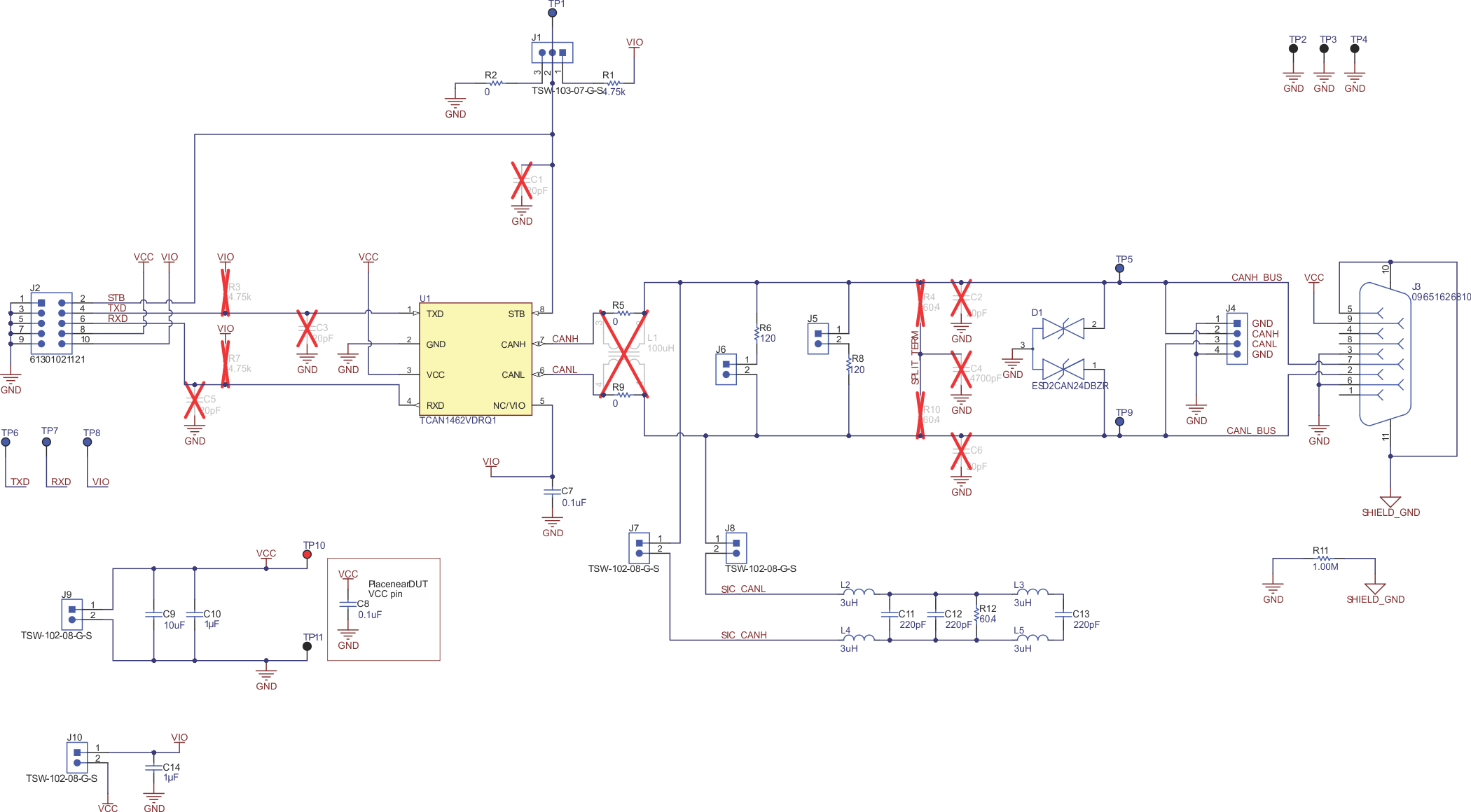
Figure 1-2 shows the EVM schematic.
 Figure 1-2 EVM
Schematic