SLLU364 may 2023 MCT8315A
- 1
- Abstract
- 1Revision History
- Trademarks
- 2Introduction
- 3Essential Controls
-
4Basic Controls
- 4.1 Device and pin configuration
- 4.2 System level configuration
- 4.3
Control configurations
- 4.3.1 Initial speed detection of the motor for reliable motor resynchronization
- 4.3.2 Unidirectional motor drive detecting backward spin
- 4.3.3 Preventing back spin of rotor during startup
- 4.3.4 Faster startup timing
- 4.3.5 Improving speed regulation
- 4.3.6 Stopping motor quickly
- 4.3.7 Faster deceleration
- 4.3.8 Preventing supply voltage overshoot during motor stop and deceleration
- 4.3.9 Protecting against rotor lock or stall condition
- 4.3.10 Maximizing thermal efficiency and increasing thermal performance
- 4.3.11 Mitigating Electromagnetic Interference (EMI)
- 4.3.12 Improving Motor efficiency
- 4.3.13 Limiting and regulating supply power
4.3.2 Unidirectional motor drive detecting backward spin
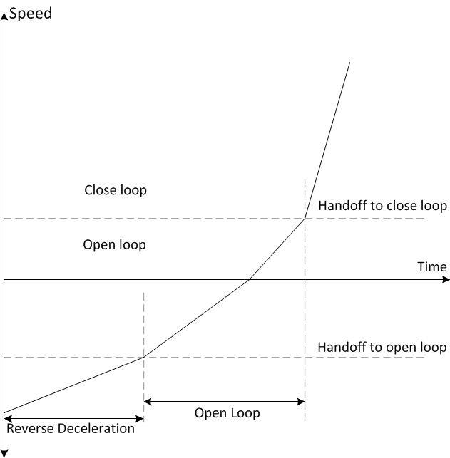
For applications that require spinning the motor in a specific direction, it is important to know if the motor is coasting or spinning in the direction opposite to the intended direction of spin. MCT8315A reverse drive function acts to reverse decelerate the motor through zero speed and to accelerate after changing direction until it transitions into closed loop as shown in Figure 4-1.
 Figure 4-1 Reverse Drive Function
MCT8315A provides an option to apply brakes and stop the motor while the motor is coasting or spinning in reverse direction and then accelerate into closed loop after changing the direction.
In applications such as ceiling fans and pumps, it is required to spin the motor in specific direction for desired results. For such applications, it is recommended to follow the below recommendations.
Step 1: Enable ISD [ISD_EN]
Step 2: Enable Motor ISD Reverse drive [RVS_DR_EN]
Step 3: Enable reverse resynchronization [RESYNC_EN]