SLLU374 November   2024 MCF8329A


  1.   1
  2.   Abstract
  3.   Trademarks
  4. 1Introduction
  5. 2Hardware Design and Setup
    1. 2.1 Board Design
      1. 2.1.1 External MOSFET Selection
      2. 2.1.2 Gate Resistor Selection
      3. 2.1.3 Bootstrap and GVDD Capacitor Selection
      4. 2.1.4 Current Shunt Resistor Selection
      5. 2.1.5 VREG MOSFET Selection
      6. 2.1.6 Additional External Power Stage Components
  6. 3Connecting to the GUI
  7. 4Spinning Into Closed Loop
    1. 4.1 Essential Configuration
      1. 4.1.1 Loading Recommended Default Values
      2. 4.1.2 Setting Base Current
      3. 4.1.3 Setting Current Limits
      4. 4.1.4 Setting Voltage Limits
      5. 4.1.5 Input the Motor's Phase Resistance and Inductance
      6. 4.1.6 Maximum Electrical Speed (Hz)
      7. 4.1.7 Run MPET to Identify Motor Parameters
        1. 4.1.7.1 Skipping MPET Measurements
    2. 4.2 Testing for Successful Startup Into Closed Loop
  8. 5Basic Controls
    1. 5.1 Speed Input Mode
    2. 5.2 Preventing Back Spin of Rotor During Startup
    3. 5.3 Faster Startup Timing
    4. 5.4 Improving Speed Regulation
    5. 5.5 Limiting and Regulating Supply Power
    6. 5.6 MTPA Tuning
    7. 5.7 Motor Studio Optimization Wizards
  9. 6Fault Handling
    1. 6.1 MPET BEMF FAULT [MPET_BEMF_FAULT]
    2. 6.2 Abnormal BEMF Fault [ABN_BEMF]
    3. 6.3 Lock Current Limit [LOCK_LIMIT]
    4. 6.4 Hardware Lock Current Limit [HW_LOCK_LIMIT]
    5. 6.5 No Motor Fault [NO_MTR]
    6. 6.6 Abnormal Speed [ABN_SPEED]

Connecting to the GUI

Before connecting the MCF8329EVM to the computer, start up the Motor Studio application and select MCF8329A from the drop down. Click on Proceed and then click on the Setup Now button for instructions on how to connect power, connect a motor, and configure the jumpers and switches on the EVM.
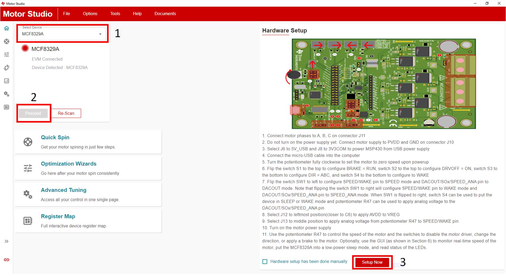
 EVM Hardware Setup Figure 3-1 EVM Hardware Setup

Once the hardware setup is completed, turn on the power supply connected to the EVM. After the PVDD LED D3 lights up connect a micro-USB to USB cable between the EVM and PC. After a few seconds, Motor Studio should connect to the EVM and the two icons outlined in Figure 3-2 will turn green. If the EVM is not connecting click the Re-Scan button.
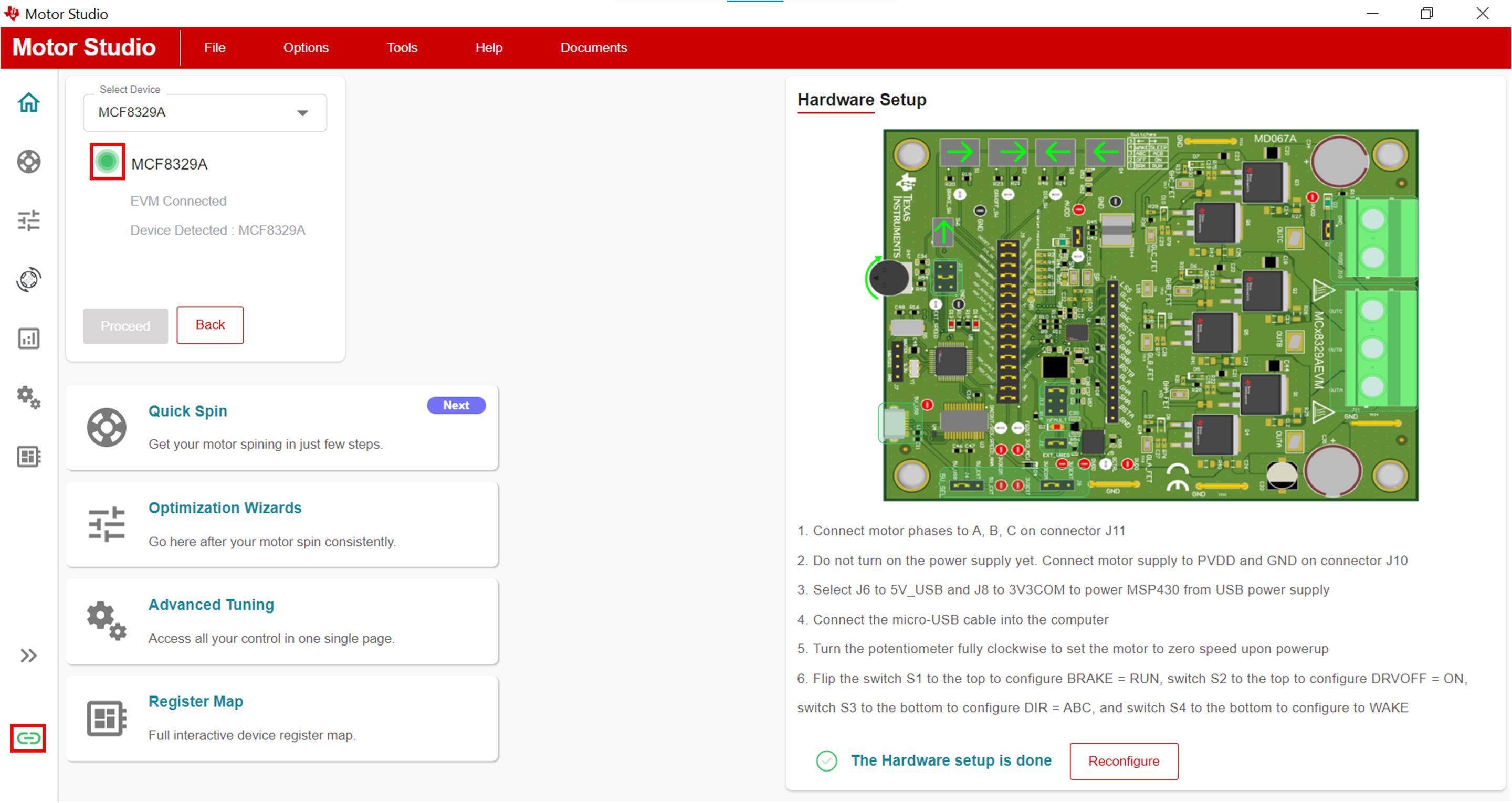
 EVM Connected
                    Indicators Figure 3-2 EVM Connected Indicators
Note: If the GUI is not able to connect to the GUI after a minute, disconnect the EVM from the PC, restart the Motor Studio GUI. After Motor Studio has started again, reconnect the EVM to the PC.