SLOS626B December 2009 – November 2015 TPA2011D1
PRODUCTION DATA.
- 1 Features
- 2 Applications
- 3 Description
- 4 Revision History
- 5 Device Comparison Table
- 6 Pin Configuration and Functions
- 7 Specifications
- 8 Parameter Measurement Information
- 9 Detailed Description
- 10Application and Implementation
- 11Power Supply Recommendations
- 12Layout
- 13Device and Documentation Support
- 14Mechanical, Packaging, and Orderable Information
12 Layout
12.1 Layout Guidelines
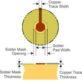
In making the pad size for the DSBGA balls, TI recommends that the layout use nonsolder mask defined (NSMD) land. With this method, the solder mask opening is made larger than the desired land area, and the opening size is defined by the copper pad width. Figure 36 shows the appropriate diameters for a DSBGA layout.
Place all the external components close to the TPA2011D1 device. Placing the decoupling capacitors as close as possible to the device is important for the efficiency of the class-D amplifier. Any resistance or inductance in the trace between the device and the capacitor can cause a loss in efficiency.
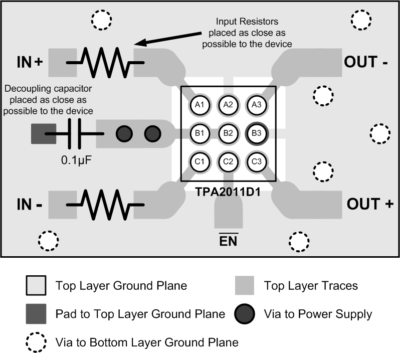
An on-pad via is not required to route the middle ball B2 (PVDD) of the TPA2011D1. Just short ball B2 (PVDD) to ball B1 (VDD) and connect both to the supply trace as shown in Figure 37. This simplifies board routing and saves manufacturing cost.
 Figure 36. Land Pattern Dimensions
Table 3. Land Pattern Dimensions(1)(2)(3)(4)
| SOLDER PAD DEFINITIONS | COPPER PAD | SOLDER MASK OPENING(5) | COPPER THICKNESS | STENCIL OPENING(6)(7) | STENCIL THICKNESS |
|---|---|---|---|---|---|
| Nonsolder mask defined (NSMD) | 0.23 mm | 0.310 mm | 1 oz max (0.032 mm) |
0.275 mm x 0.275 mm Sq. (rounded corners) |
0.1 mm thick |
12.2 Layout Example
 Figure 37. TPA2011D1 Layout Example