SLUAA69 July 2020 – MONTH TPS548D22
1.1 LED Driver Methods
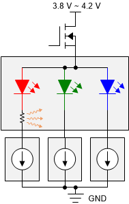
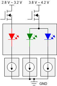
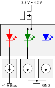
The LED forward voltage varies by color. Typically, 1.8 V to 2.2 V for red LED and 2.8 V to 3.4 V for both blue and green LEDs. Figure 1-1, Figure 1-2, and Figure 1-3 show three types of LED driver solutions:
- traditional common-anode
- traditional common-cathode
- new common-cathode
 Figure 1-1 Traditional Common-Anode LED Display
  Figure 1-2 Traditional Common-Cathode LED Display
  Figure 1-3 New Common-Cathode LED Display
 The traditional common-anode LED display (shown in Figure 1-1) uses a single power rail for all three LED colors. The red LED required an additional external resistor in series to limit the voltage across the red LED. The disadvantage is extra power loss due to the resistor. An approach to eliminate the resistor is using common-cathode LED display with red, blue, and green LEDs powered by separate rails, as shown in Figure 1-2 and Figure 1-3.
The traditional common-cathode LED display (drive common-cathode LEDs) shown in Figure 1-2 has two power supplies. One is dedicated to the red LED. The other is for both the blue and green LEDs with ground as a common reference. This power supply is called a common-cathode power supply since the reference is ground (cathode).
The new common-cathode LED display (drive common-anode LEDs) shown in Figure 1-3 uses one supply connected to a common anode for all three LEDs and a second supply that generates a bias voltage for the red LED. This power supply is called a common-anode power supply because the reference is positive to the supply (anode). The key challenge is to generate the 1-V bias supply for the red LED.
Common-anode RGB LEDs share a single electrical connection for the anode of all three LEDs and are powered by a single power supply. Common-cathode RGB LEDs have two power supplies – one for the red LED and one for the blue and green LEDs with ground as a common reference. One supply is dedicated to the red LED and the other supply powers both the blue LED and the green LED. The improved common-cathode LED display uses one supply connected to a common anode for all three LEDs and a second supply that generates a bias voltage for the red LED. The key challenge is to generate the 1-V bias supply for the red LED.
For a video or image display application, red LEDs can typically occupy between 40% and 50% of the driver current. With the common-cathode LED driving method, the LED display surface temperature can be significantly reduced by more than ten degrees. This method enables color uniformity and improved LED life. In addition, power consumption can be reduced between 30% and 75%.