SLUUBX7A August 2018 – January 2024 TPS560430-Q1
4 Board Layout
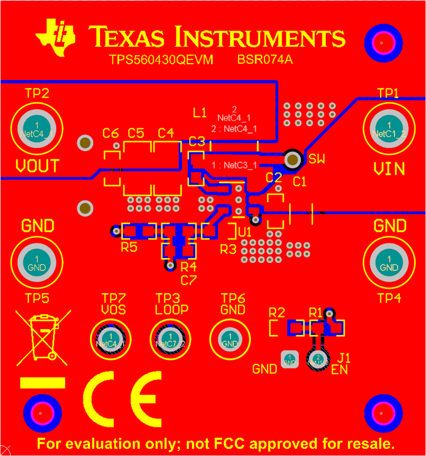
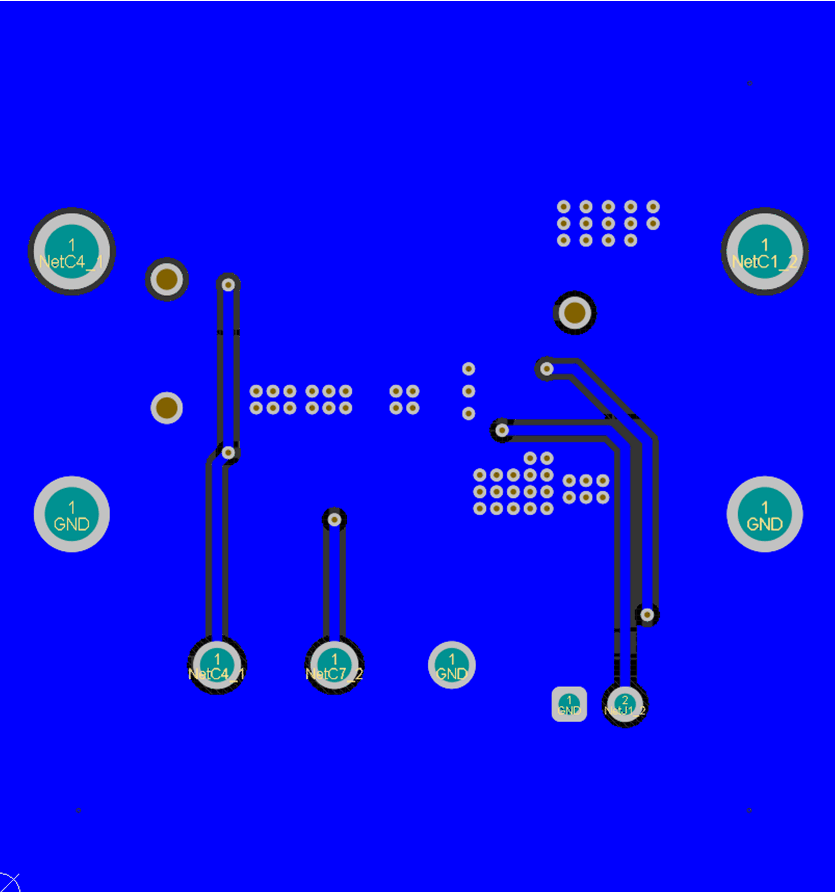
Figure 4-1 and Figure 4-2 show the board layout for the TPS560430QEVM. The PCB consists of a 2-layer design. The board size is 38 mm x 41 mm, 1-oz copper planes is applied on both layers.
 Figure 4-1 Top Layer
 Figure 4-2 Bottom Layer