SLUUC21A July   2019  – July 2021 TPS62866


  1. 1Introduction
    1. 1.1 Performance Specification
    2. 1.2 Modifications
  2. 2Setup
    1. 2.1 Input/Output Connector Descriptions
    2. 2.2 Setup
  3. 3TPS62866EVM-051 Test Results
  4. 4Board Layout
  5. 5Schematic and List of Materials
    1. 5.1 Schematic
    2. 5.2 List of Materials
  6. 6Software User Interface
    1. 6.1 Software Setup
    2. 6.2 Interface Hardware Setup
    3. 6.3 User Interface Operation
      1. 6.3.1 Home Screen
      2. 6.3.2 Settings Screen
      3. 6.3.3 Register Map Screen
  7. 7Revision History

Board Layout

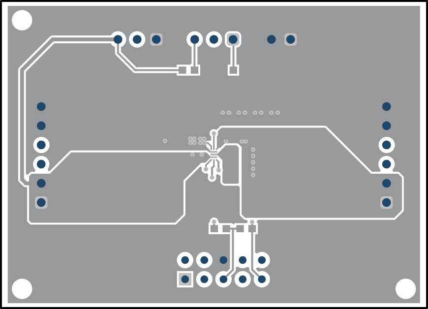
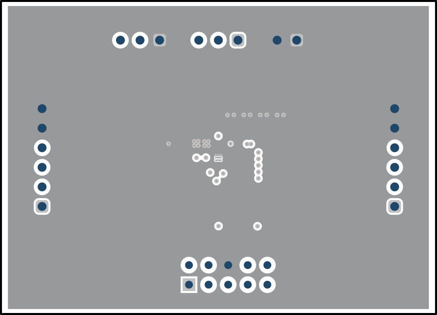
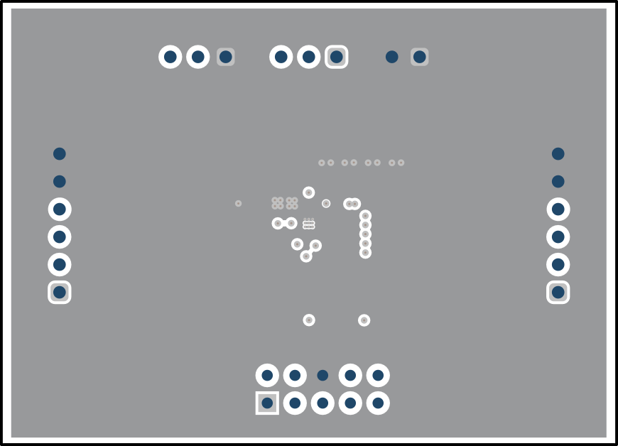
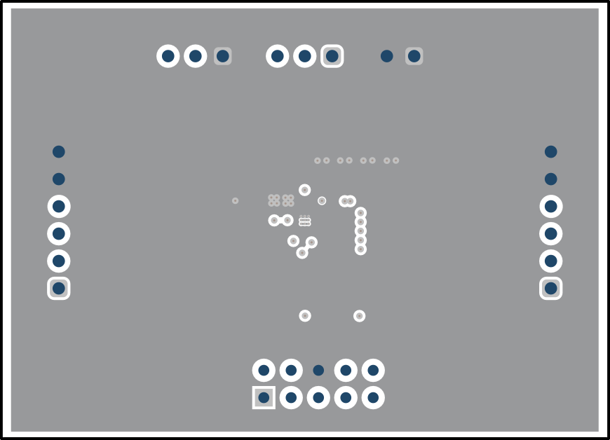
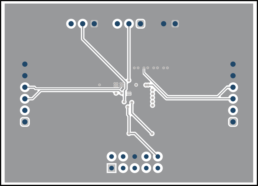
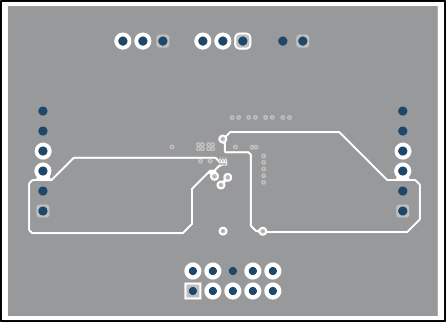
This section provides the TPS62866EVM-051 board layout and illustrations in Figure 4-1 through Figure 4-7. The Gerbers are available on the EVM product page: TPS62866EVM-051
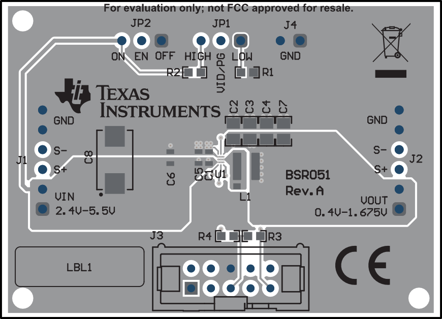
GUID-4EDEE2BB-FF58-44D6-BBF1-D69734508E39-low.gifFigure 4-1 Top Assembly
GUID-131F946B-6D61-4EDD-AD7D-E7D303E47BBA-low.gifFigure 4-2 Top Layer
GUID-B8D2BA2D-677F-4ACF-97EF-31E2A2F73CCB-low.gifFigure 4-3 Signal Layer 1
GUID-3D57AF8A-B034-4FE5-B3E1-E895D722C658-low.gifFigure 4-4 Signal Layer 2
GUID-974BEA63-83C1-49FB-8012-072C7FA83BC0-low.gifFigure 4-5 Signal Layer 3
GUID-AC6AF0A2-81F5-4FBF-810D-F92C4985AC62-low.gifFigure 4-6 Signal Layer 4
GUID-15E45403-3B3A-4A8C-9FB7-6314AAD40C28-low.gif Figure 4-7 Bottom Layer
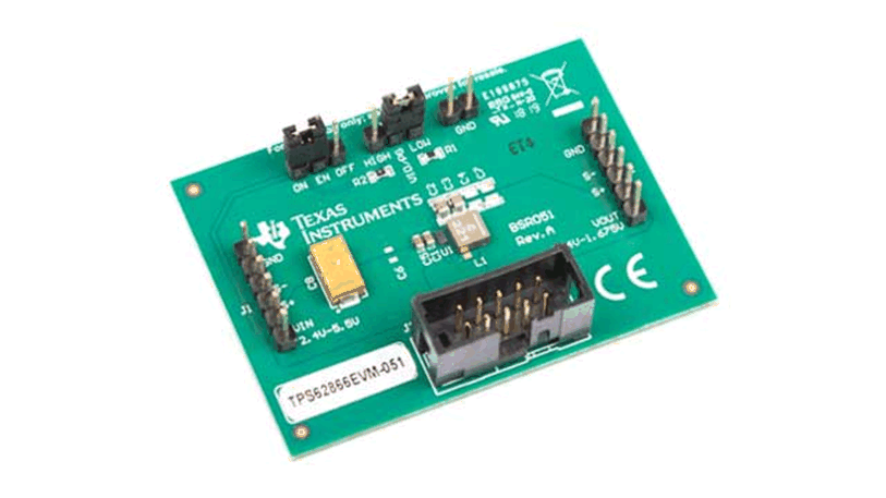
GUID-49B2899F-5A5A-47A8-B9EF-DABD4145CF10-low.gifFigure 4-8 TPS62866EVM-051 Angled View
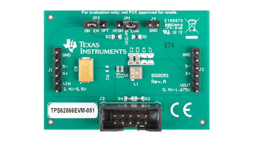
GUID-42816EE9-F243-4591-A5E6-DC80C7537601-low.gifFigure 4-9 TPS62866EVM-051 Overhead View