SLUUC53A
October 2020 – March 2021
BQ25300
,
BQ25302
,
BQ25303J
Trademarks
1
Introduction
1.1
EVM Features
1.2
I/O Descriptions
2
Test Setup and Results
2.1
Equipment
2.2
Equipment Setup
2.3
Test Procedure
2.3.1
Initial Settings
2.3.2
Precharge Mode Verification
2.3.3
Fast Charge Mode Verification
2.3.4
Battery Temperature Monitoring Verification
2.3.5
Evaluation Results
2.3.6
Helpful Tips
3
PCB Layout Guideline
4
Board Layout, Schematic, and Bill of Materials
4.1
Board Layout
4.2
Schematic
4.3
Bill of Materials
5
Revision History
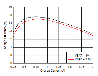
2.3.5
Evaluation Results
f
SW
= 1.2 MHz
Inductance 1 μH
V
BUS
= 5 V
Inductor DCR = 14.6 mΩ
Figure 2-2
BQ25302EVM 1-Cell Battery Charge Efficiency vs. Charge Current
f
SW
= 1.2 MHz
Inductance = 2.2 uH
V
BAT
= 3.8 V
Inductor DCR = 20 mΩ
Figure 2-3
BQ25300EVM, BQ25303JEVM 1-Cell Battery Charge Efficiency vs. Charge Current