SLUUC53A October 2020 – March 2021 BQ25300 , BQ25302 , BQ25303J
2.2 Equipment Setup
- Review EVM connections in Table 1-2.
- Set PS1 for 5-V DC, 2-A current limit and then turn off the supply.
- Set PS2 for 3-V DC, 2-A current limit and then turn off the supply.
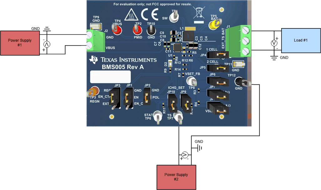
- Connect the output of PS1 to J2 (VBUS and PGND) as shown in Figure 2-1.
- Connect a voltage meter across TP4 (VBUS) and TP9 (PGND), or across J2.
- Turn on Load #1 as shown in Figure 2-1, set to constant voltage mode, and output to 2.5 V. Disable Load.
- Connect one voltage meter across TP5 (BAT) and TP11 (PGND) or across J1-3 and J1-1 as shown in Figure 2-1.
- Connect one voltage meter across TP2 (PMID) and TP10 (PGND).
- Connect the output of PS2 to TP7 (TS) and TP12 (PGND) as shown in Figure 2-1.
- Install shunts as shown in Table 1-3.
 Figure 2-1 Original Test Setup for BMS005