SLUUCB4 June 2020 TPS25980
5 Test Setup and Procedures
In this user guide, the test procedure is described for TPS259804O device. Following similar test steps, TPS259802O/3O/7O variants from TPS25980x family can also be evaluated.
Make sure the evaluation board has default jumper settings as shown in Table 6.
Table 6. Default Jumper Setting for TPS25980EVM eFuse Evaluation Board
| J4 | J6 | J7 | J8 | J9 | J10 | J11 | J12 |
|---|---|---|---|---|---|---|---|
| Open | 1-2 | 2-3 | Install | 3-4 | 5-6 | Open | 1-2 |
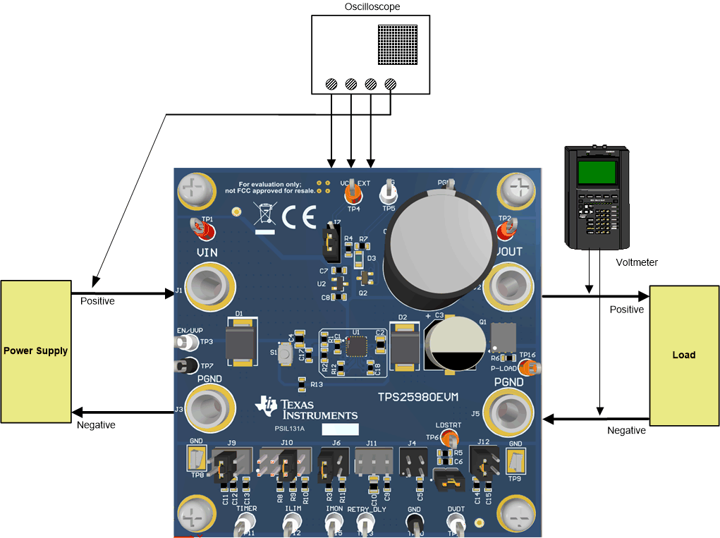
 Figure 2. TPS25980EVM Setup with Test Equipment
 Follow these instructions before starting any test and repeat again before moving to next test:
- Set the power supply output (VIN) to zero volts.
- Turn ON the power supply and set the power supply output (VIN) to 12 V, current limit = 20 A.
- Turn OFF the power supply.
- Set the jumper setting on EVM to default position as shown in Table 6.