SLUUCB5E June 2020 – July 2022 BQ25792 , BQ25798
2.4.2 Communication Verification
If using Battery Management Studio, use the following steps for communications verification:
- In Battery Management Studio, select "READ REGISTER" at the top of the page. "Device ACK OK" should appear at the top of the page.
- Select Field View in the top right of the screen. Note there are two tabs, one for 8-bit registers and one for 16-bit registers. In the 8-bit tab, there are sections for chip, charger and OTG single-bit and multi-bit registers. In the 16-bit tab are the charger and OTG multi-bit registers for setting voltages and currents. In addition, the ADC registers are on the 16-bit tab.
- Prepare the charge mode charger
register settings in the following way if not already set there by default:
- On the 8-bit
Registers tab in the Chip Config Single-bit Registers
section
- Change Watchdog Timer to disabled
- Check the "ShipFET Present?" check box
 Figure 2-2 Single-Bit
Registers Section
 - On the 8-bit
Registers tab in the Charger Multi-bit Registers
section
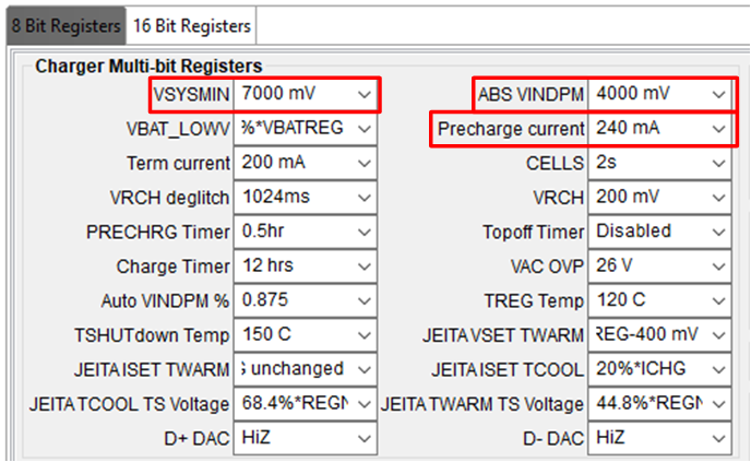
- Set the Precharge current to 240 mA
- Set ABS VINDPM to 4000 mV
- Set VSYSMIN to 7000 mV
 Figure 2-3 Multi-Bit
Register Section
 - On the 16-bit
Registers tab in the Charger Multi-bit Registers
section
- Set the Charge Voltage charging regulation limit to 8400 mV
- Set the Charge Current to 500 mA.
- Set the input current regulation limit (IINDPM) to 3000 mA.
 Figure 2-4 16-Bit Register
Section
 - On the 8-bit
Registers tab in the Chip Config Single-bit Registers
section
If using TI Charger GUI, follow these steps.
- In the TI Charger GUI homepage,
select the charger you are using. You should see at the bottom-left, Hardware
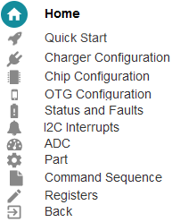
Connected. Here is a brief description of what the icons on the left side panel
mean:

Figure 2-5 Icon GuideNote: If the EVM is powered but not communicating (for example, does not ACK), try updating the USB2ANY firmware to the latest version using the software at https://www.ti.com/lit/zip/slvc695. The software tells you to press the reset button, on the opposite side of the USB connector to the LED, using a paper clip or narrow pin. - Go to the Chip Configuration and
set the Watchdog Timer to disabled and check the "ShipFET present?" box.
 Figure 2-6 Chip
Configuration
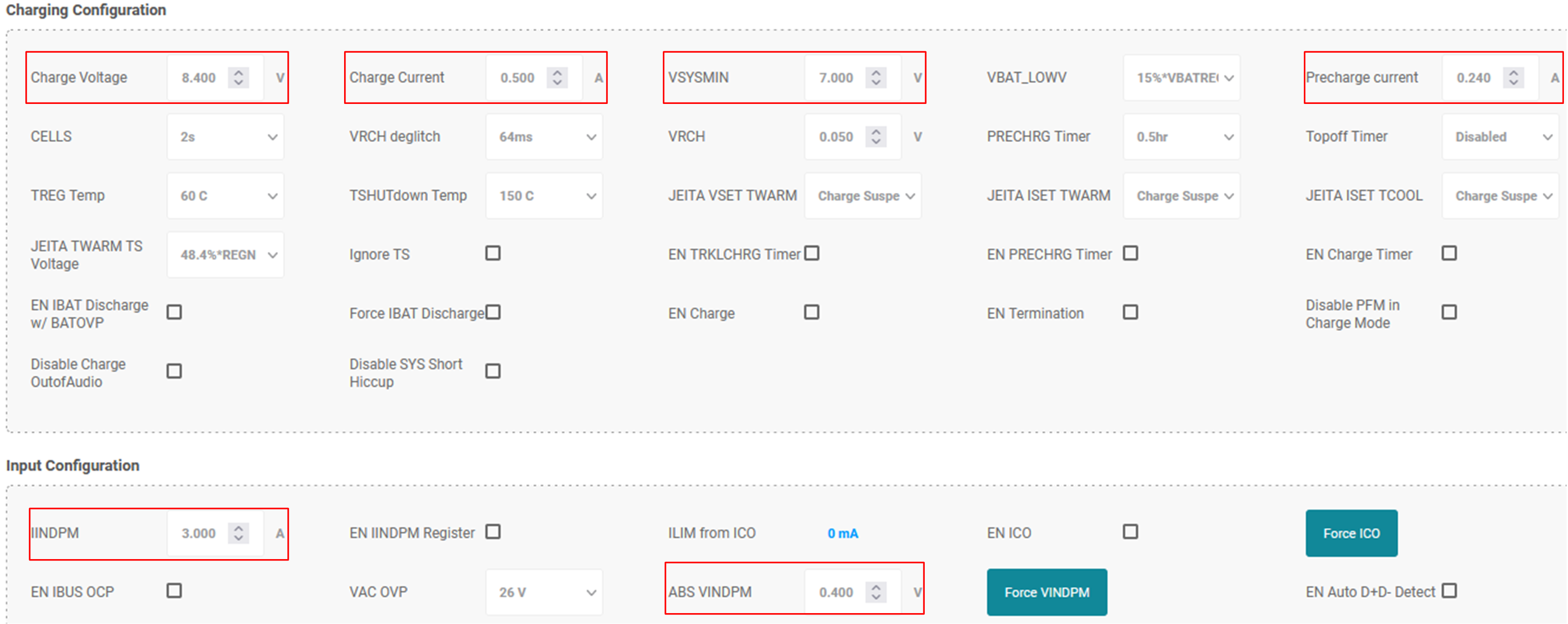
 - Go to the Charger Configuration
and set
- VSYSMIN to 7 V
- Charge Voltage to 8.4 V
- Charge Current to 0.5 A
- Precharge current to 0.24 A
- IINDPM to 3 A
- ABS VINDPM to 0.4 V
 Figure 2-7 Charger
Configuration