SLUUCB5E June 2020 – July 2022 BQ25792 , BQ25798
2.2 Equipment Setup
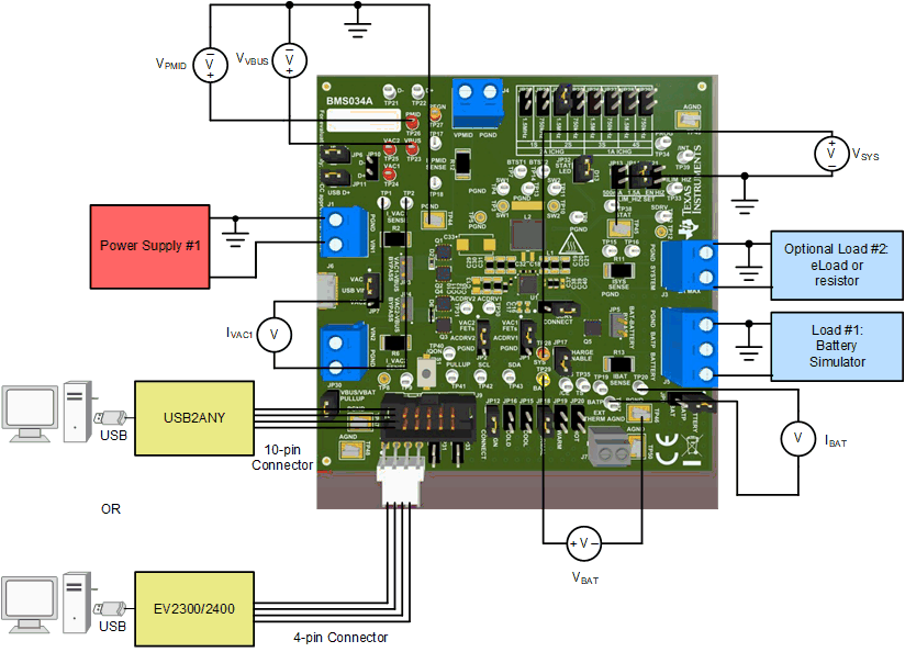
Use the following list to set up the EVM testing equipment. Refer to Figure 2-1 for the test setup connections to the EVM:
- Review the EVM connections in Table 1-2.
- Set PS#1 for 5.0-V, 3-A current limit and then turn off the supply. Connect PS#1 to J1 (VIN1 and PGND).
- Connect a voltage meter across TP23 (VBUS) and TP44 (PGND) to measure the input voltage as seen from the VBUS pins of the charger.
- Connect a voltage meter across TP1 and TP2 (I_VAC1_SENSE) to measure the input current into the VBUS pins through the VIN1 path. Alternatively, you may connect a current meter between PS1 and J1.
- Set Load #1 to constant voltage mode, capable of sinking (for example, compliance) at least 3 A, and output to 5.0 V, and then disable load. Connect Load #1 to J5 (BATTERY and PGND).
- Connect a voltage meter across TP29 (BAT) and TP46 (PGND) to measure the battery voltage as seen from the BAT pins of the charger.
- Connect a voltage meter across TP19 and TP20 (I_BAT_SENSE) to measure the battery charge current out of and discharge current into BAT pins. Alternatively, you may connect a current meter between Load #1 and J5.
- Connect a voltage meter across TP28 (SYS) and TP45 (PGND) to measure the system voltage as seen from the SYS pins of the charger.
- Install shunts as shown in Table 1-3.
 Figure 2-1 Equipment Test Setup for Testing
Battery Charging