SLUUCK9 april 2023 TPSM843B22
3.6 Start-up and Shutdown with EN
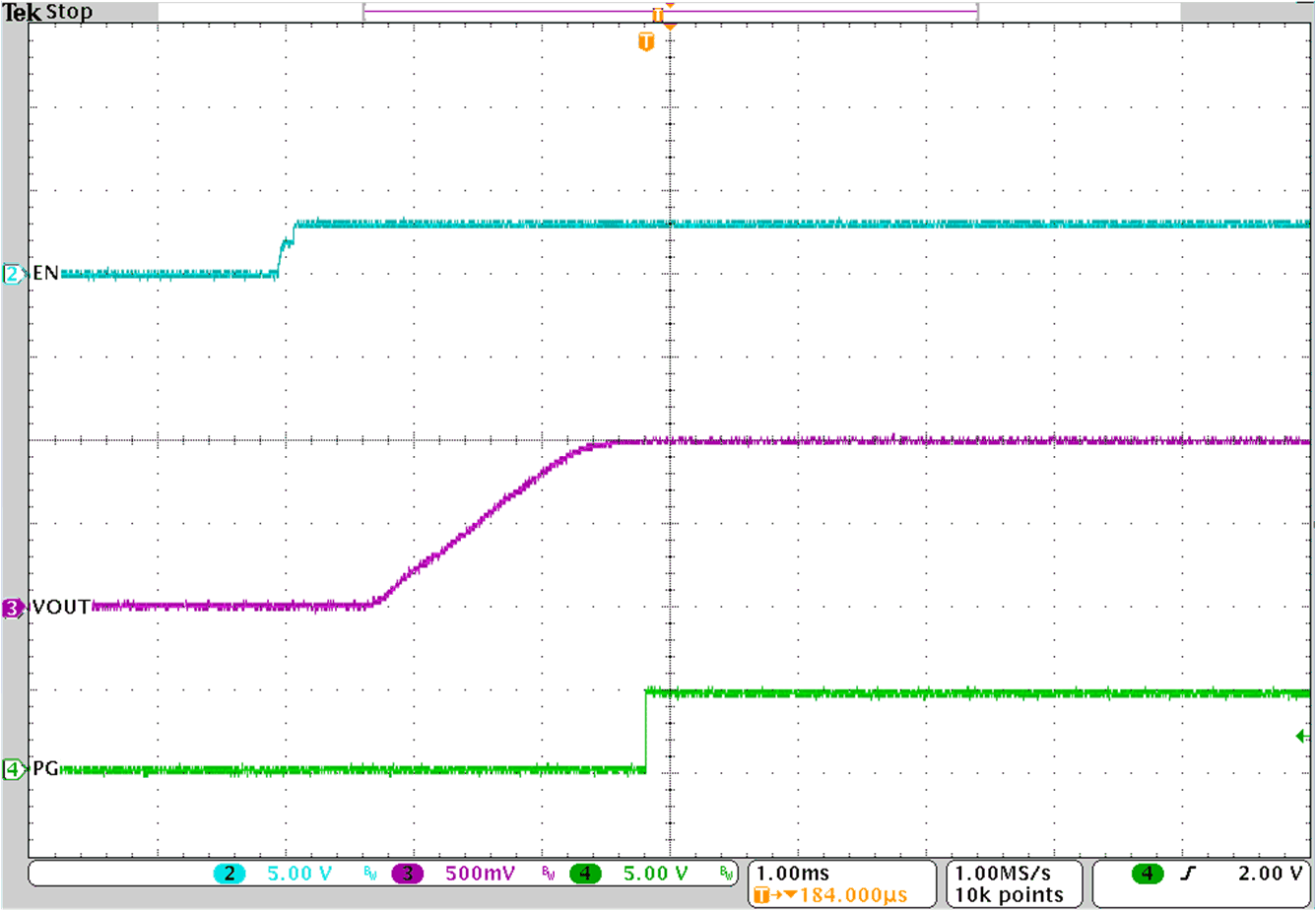
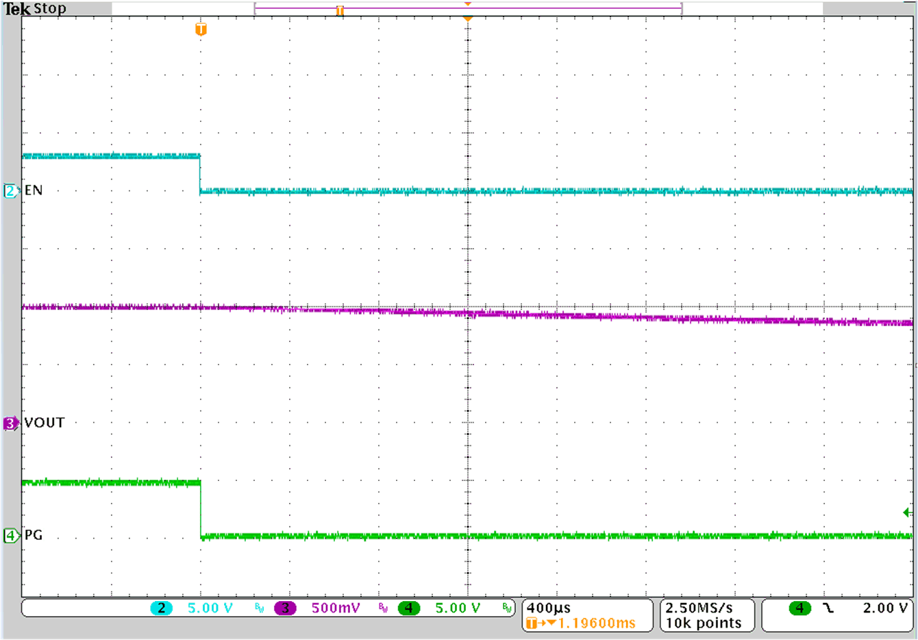
Figure 3-14 and Figure 3-15 show the start-up and shutdown waveforms with EN. In Figure 3-14, the input voltage is initially applied and the output is inhibited by pulling EN to GND. When the EN voltage is increased above the enable-threshold voltage, the start-up sequence begins and the output voltage ramps up to the externally set value.
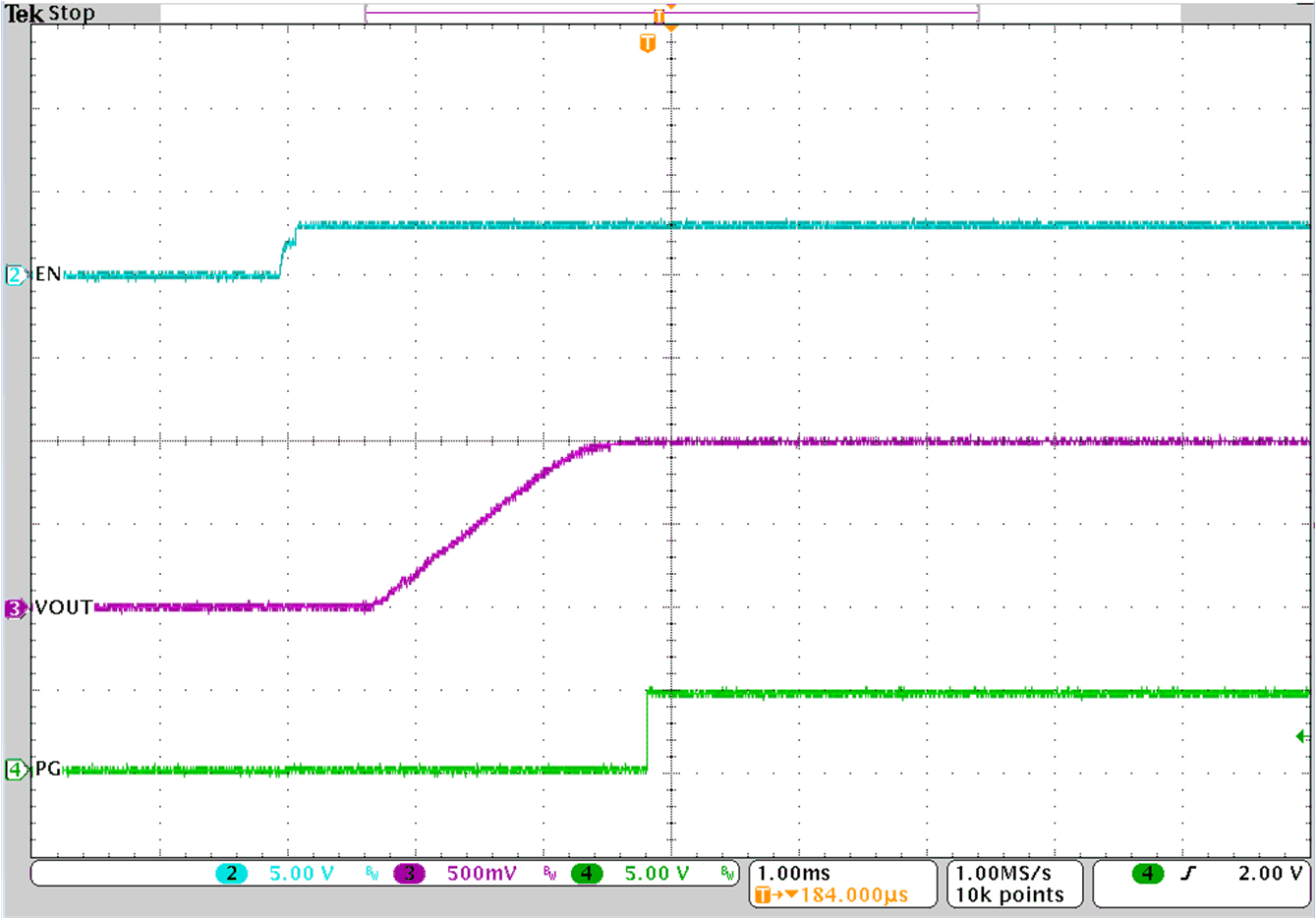
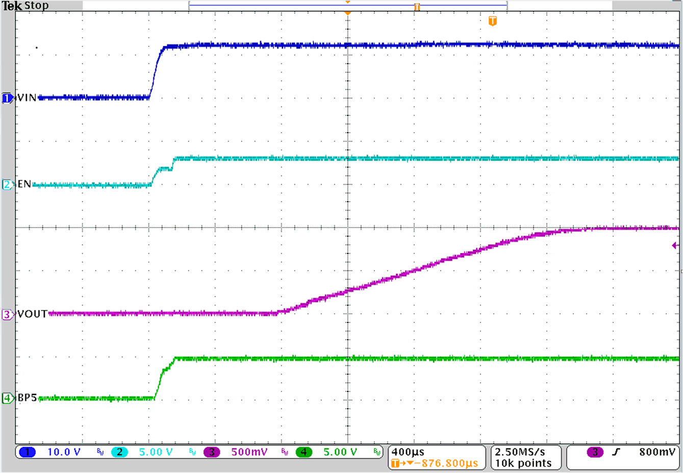
Figure 3-16 shows EN start-up with a 10-A load.Figure 3-17 shows the BP5 internal LDO start-up relative to the EN pin.
A shunt on the EN jumper J2 can be used to test the EN start-up of U1. When the shunt is removed from EN jumper J2 or place on pin 1 and 2 of EN jumper J2, EN is released and the start-up sequence begins for U1.
 Figure 3-14 U1 Start-up with EN – No Load
 Figure 3-16 U1 Start-up with EN – 10-A
 Figure 3-15 U1 Shutdown with EN – No Load
 Figure 3-17 U1 Startup with EN – No Load and Measuring BP5