SLUUCP7A August 2023 – March 2024 LMR51606
2.1 Input and Output Connector Description
VIN — Terminal TP1 – Power input terminal for the converter. Adjacent to this terminal is the GND reference ground. Use this terminal to attach the EVM to a cable harness.
VOUT — Terminal TP3 – Regulated output voltage for the converter. Adjacent to this terminal is the GND reference ground.
GND — Terminal TP2, TP4 – Ground reference for the converter. Use these terminals to attach the EVM to a cable harness.
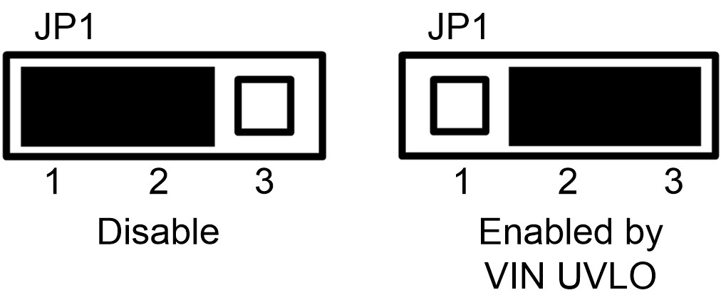
ENABLE SETTING — Jumper JP1 – Used to enable the switch-mode converter. The device enables when the EN pin is high, and disabled when low.
 Figure 2-1 Enable Jumper Setting
Testpoint — TP6, TP7, TP9, Test points used for loop response measurements