SLUUCX0A February   2024  – June 2024 UCC57108


  1.   1
  2.   Description
  3.   Features
  4.   4
  5. 1Evaluation Module Overview
    1. 1.1 Introduction
    2. 1.2 Kit Contents
    3. 1.3 Specification
    4. 1.4 Device Information
  6. 2Hardware
    1. 2.1 Recommended Power Requirements
    2. 2.2 I/O Description
    3. 2.3 Jumper Description
    4. 2.4 Setup for Different UCC57108 Variants
    5. 2.5 DESAT Setup
  7. 3Implementation Results
    1. 3.1 Out-The-Box Evaluation
    2. 3.2 Equipment Setup
      1. 3.2.1 Power Supply
      2. 3.2.2 Function Generator
      3. 3.2.3 Oscilloscope
      4. 3.2.4 Digital Multimeter (DMM)
    3. 3.3 Bench Setup
    4. 3.4 Procedure and Results
  8. 4Typical Performance Waveforms
    1. 4.1 DESAT Feature
    2. 4.2 Bipolar Feature of UCC57108B
  9. 5Hardware Design Files
    1. 5.1 Schematics
    2. 5.2 PCB Layouts
    3. 5.3 Bill of Materials
  10. 6Compliance Information
  11. 7Additional Information
    1. 7.1 Trademarks
  12. 8Revision History

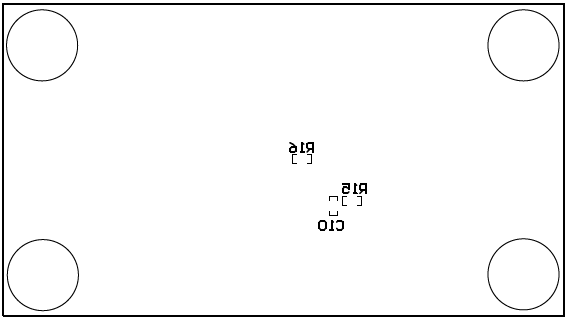
PCB Layouts

Figure 6-2 through Figure 6-5 show the PCB layout information for the UCC57108EVM.

UCC57108EVM Top Overlay Figure 5-2 Top Overlay
UCC57108EVM Top Layer Figure 5-3 Top Layer
UCC57108EVM Bottom Overlay Figure 5-4 Bottom Overlay
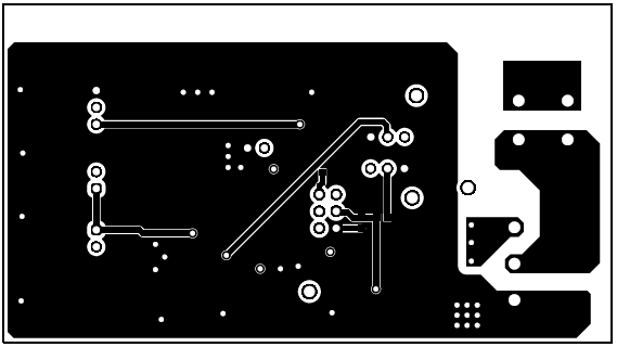
UCC57108EVM Bottom Layer Figure 5-5 Bottom Layer