SLUUD36A July 2024 – August 2024 BQ25820
2.4.3 Equipment Setup - Using a CV Load

Use the following guidelines to set up the equipment:
- Set power supply 1 for 40V DC, 8A current limit and then turn off the supply.
- Connect the output of power supply 1 in series with a current meter to J1 (VIN and PGND).
- Connect a voltage meter across J1 (VIN) and J1 (PGND).
- Connect load 1 in series with a current meter to J3 (VOUT and PGND).
- Connect a voltage meter across J3 (VOUT and PGND).
- Set electronics load to CV mode
and 23.5V. Turn off load 1.Note: Add a 3000uF capacitor on BAT pin when testing without real battery.
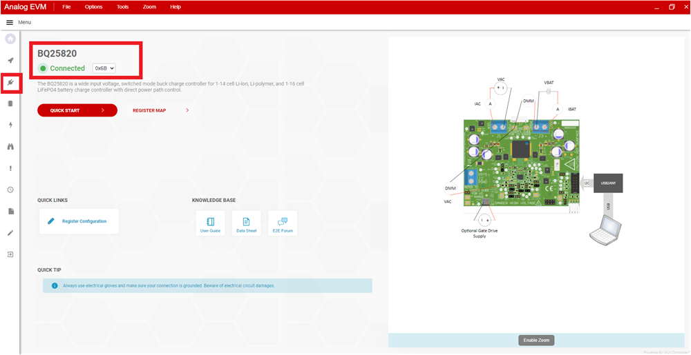
- Connect J5 to the EV2400. Connect J5 to the I2C PORT 2 on the EV2400.
- Make sure the jumpers are installed as indicated in IO and Jumper Descriptions.
- Unplug Jumper 13.
- If using Battery Management
Studio, then use the following steps:
- Connect J5 to the EV2400. Connect J5 to the I2C PORT 2 on the EV2400
- Turn on the computer and load 2. Open the bqStudio software.
- Select Charger and
click the Next button.
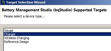
- Select Charger_1_00_BQ25820.bqz on the Select a Target Page.
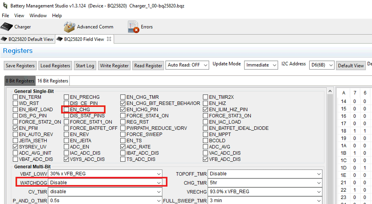
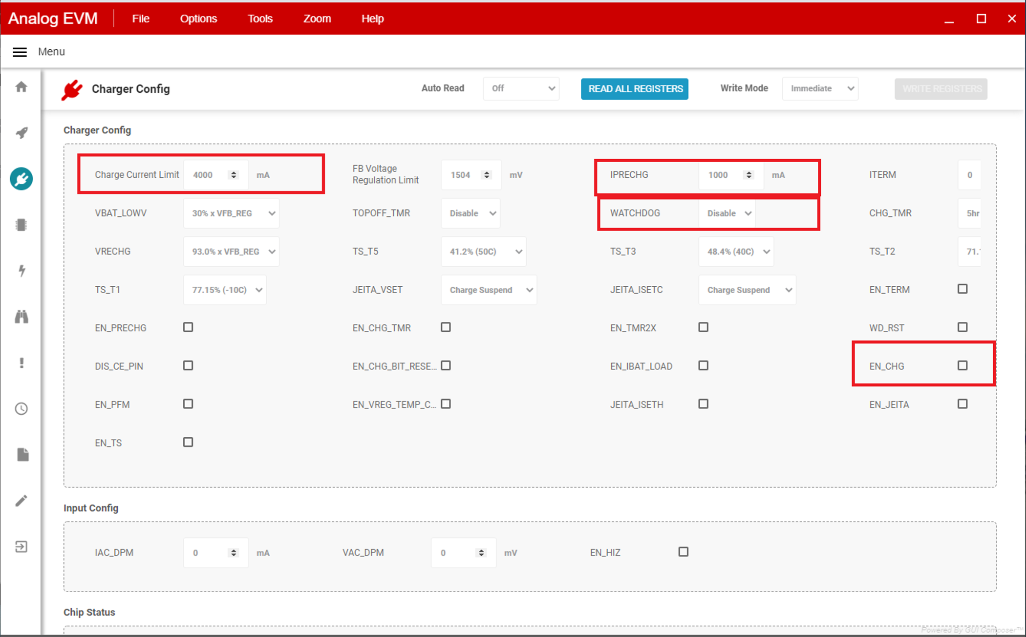
- After selecting the target device, click Field View. and then click the Read Register button.
- Set WATCHDOG and EN_CHG
to disabled.
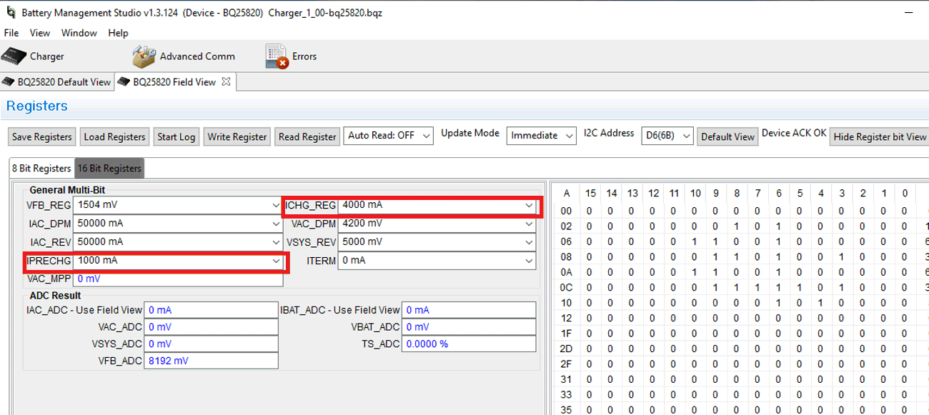
- In 16 Bit
Registers, set ICHG_REG to 4000mA and IPRECHG to 1000mA.
- If using TI Charger GUI, then use
the following steps:
- Connect J4 to the USB2ANY. Turn on the computer and load 2.
- Navigate to the TI Charger GUI website and select the
charger to use:
- At the top left of the
screen, users will see the Hardware Connected icon. After users
see the hardware is connected, select the plug icon on the left
panel.
- This is the Charger Configuration window. Click the Read All
Register button at the top, then set WATCHDOG and EN_CHG to
disabled. Set ICHG_REG to 4000mA and IPRECHG to 1000mA.
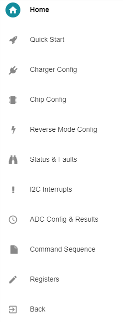
- Here is a brief
description of what the other icons on the left side panel are. Select
through these icons to configure other operations of the battery
charger.
- Set EN_CHG to enabled. Plug in jumper 13.
- Set power supply 1 to 40V,
measure
V(J1(VAC)) = 40V ± 0.5V
I(J1(IAC)) = 1.2A ± 0.5A
V(J3(VBAT)) = 23. V ± 0.5VI(J3(IBAT)) = 2A ± 0.5A
Use the following guidelines to test the BQ25820 EVM power path:
- Disconnect the power supply from J1 (VIN and PGND) and disconnect Load 1 from J3 (VOUT and PGND).
- Connect the output of power supply 1 to J3 (VOUT and PGND).
- Set power supply 1 for 20V DC, 8A current limit and then turn off power supply.
- Connect a voltage meter across J2 (VSYS) and J2 (PGND).
- Turn on power supply 1, measure V(J2(VSYS)) = 20V ± 0.5V.