SLVAED3A July 2019 – April 2024 TPS568230
2.1 Switching Loss
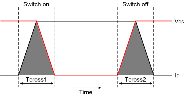
Switching losses are associated with the transition of the switch from its on-state to off-state, and back. Figure 2-1 is a complete switching process with regards to inductive load. It shows drain current and drain voltage with respect to time. Tcross by definition is the time for both the voltage and the current to complete their transients[2].
 Figure 2-1 The Voltage and Current Waveform When Switching an Inductive Load
As shown in Figure 2-1, the area enclosed by the voltage, current, and time axis is the power loss of MOSFET during the transition. The power loss in single cycle is derived in Equation 1.
where
- VDSmax is the voltage across the switch (when it is OFF)
- IDmax is the current through it (when it is ON)
- tcross is the crossover time during turn-on and turn-off, respectively
The buck converter has a filter inductor in the output side, so it meets the switching loss equation above. Equation 2 shows the inductive switching loss when switching repetitively. The higher the switching frequency, the greater the number of times the switch changes state per second, therefore, these losses are proportional to the switching frequency.
where
- Vin is the input voltage
- fsw is the switching frequency