SLVAFG5 November 2022 TPS929240-Q1
3.1 Test Set-up
Figure 3-1 shows the specific hardware connections between evaluation board and test equipment.
Both power supply and CAN bus wiring harnesses are included in the injection probe. In
this test, connections to MSP430 microcontroller monitoring electromagnetic interference
reactions of the DUT is accomplished by using fibre optics leads.  Figure 3-2 Overall Set-up of BCI
Test
 Figure 3-4 Injection Probe Side of
BCI Test
 Figure 3-3 Power Supply Side of BCI
Test
 Figure 3-5 DUT Side of BCI
Test
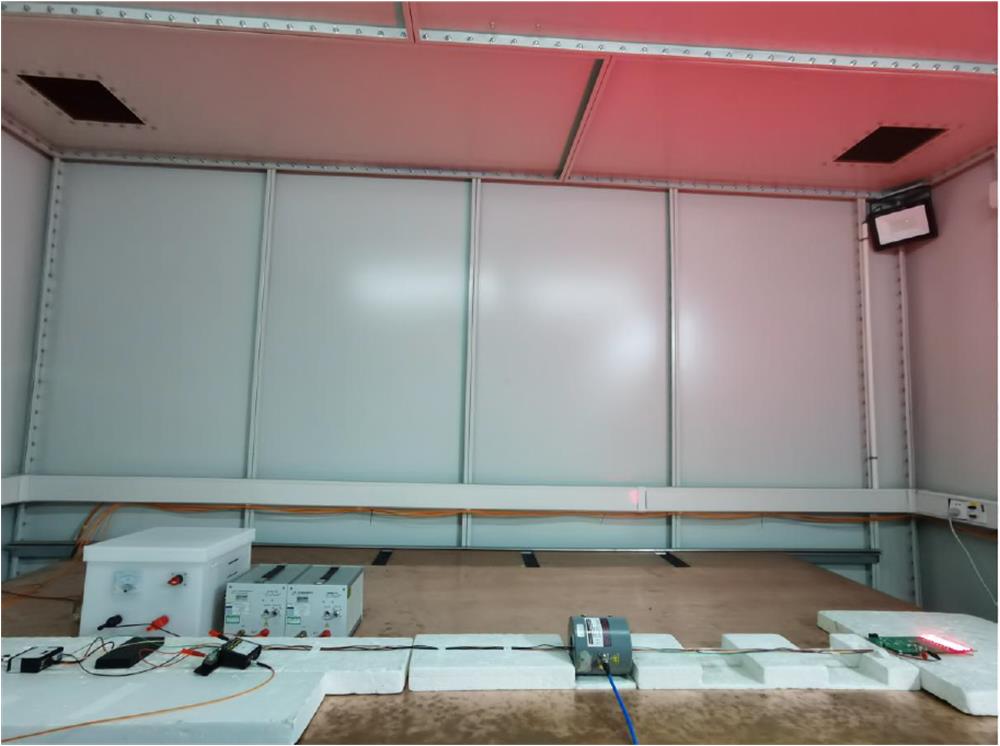
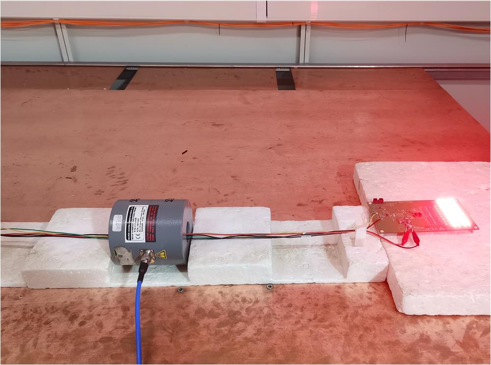
Figure 3-2 to Figure 3-5 show the equipment and EVM configuration of the BCI test.
Figure 3-1 BCI Test Set-up
 Figure 3-2 Overall Set-up of BCI
Test
 Figure 3-4 Injection Probe Side of
BCI Test
 Figure 3-3 Power Supply Side of BCI
Test
 Figure 3-5 DUT Side of BCI
Test