SLVAFG6B December 2022 – November 2024 TPS25762-Q1 , TPS25772-Q1
3.3 Hybrid Mode
Hybrid Mode is an optional power policy that behaves as a hybrid of the Assured Capacity Policy and Shared Capacity Policy. It provides the benefit of the Assured Capacity Policy by initially advertising the Port Max Power when one Sink is connected, while allowing equal distribution of the System Max Power, similar to the Shared Capacity Policy, when two Sinks are connected.
There are some Sink devices that request power based on the first Source Capabilities received and do not attempt to renegotiate for a more favorable contract when higher PDOs are offered in following Source Capabilities messages. This is a problem when FSP is desired, where Source ports are configured as Shared Capacity and Port Min Power is advertised in the initial Source Capabilities message. With Hybrid Mode, FSP is possible while ensuring that a Sink's power requirements are met.
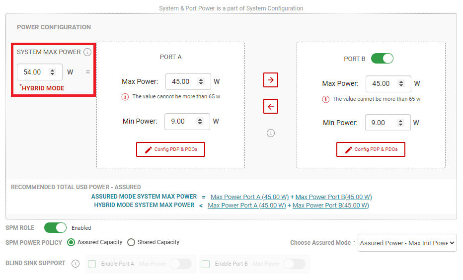
Hybrid Mode can be enabled from the Advanced Configuration view. After the SPM Engine parameters are entered with Assured Capacity Policy selected, Hybrid Mode can be enabled by modifying the System Max Power to a value less than the sum of Port A and Port B's Max Power. The GUI then displays Hybrid Mode in red text to indicate that Hybrid Mode is active as shown in Figure 3-6.
 Figure 3-6 Hybrid Mode GUI Selection -
Advanced Configuration
Figure 3-6 Hybrid Mode GUI Selection -
Advanced ConfigurationThe Hybrid Mode parameters shown in Table 3-5 are used in the power distribution method.
| Hybrid Mode Parameters | Description |
|---|---|
| Equally Divided System Power | Equally divided System Max Power allocated to each port when two
PD-Sinks are connected: System Max Power / Total number of ports. |
| Single Port Max Power Capacity | Maximum VBUS power for a port when a single PD-Sink is connected:
|
| Non-PD USB-C Power | USB Type-C 5V output for non-PD based USB Type-C charging; 7.5W or 15W. |
The typical flow of the Hybrid Mode power distribution is as follows:
- The first connected Source port initially advertises Port Max Power and sends a Get Sink Capabilities request
- The Sink responds by returning the Sink Capabilities and receives power accordingly (up to the Single Port Max Power Capacity).
- The second Source port connects to another Sink and the SPM Engine immediately distributes the Equally Divided System Power to each Port Partner. Unlike FSP, any unused remaining power does not get stored in Power Reserve and allocated to the other port.
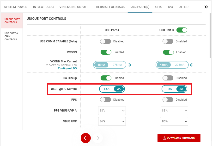
In the event where one PD Sink and one non-PD Sink are connected to the ports, the Equally Divided System Power is initially allocated to each Sink. This connection takes roughly 8.5 seconds for the TPS257xx-Q1 firmware to identify a non-PD Sink. Once a non-PD Sink is identified, the SPM Engine can reallocate and redistribute system power; Non-PD USB-C Power is distributed to the non-PD Sink and the remaining power (the difference between the System Max Power and the Non-PD USB-C Power) is allocated to the PD Sink. The Non-PD USB-C Power can be selected by configuring the USB Type-C Current parameter from the GUI's USB PORT(S) window (see Figure 3-7).
 Figure 3-7 USB Type-C Current – Advanced
Configuration
Figure 3-7 USB Type-C Current – Advanced
ConfigurationFor example scenarios of Hybrid Mode to better understand this mode's power distribution method, see Section 5.3.