SLVAFI8 February 2023 TLC6C5748-Q1
- Abstract
- Trademarks
- 1Introduction
-
2Design Considerations for Low EMI
- 2.1 Design Considerations Overview
- 2.2
Considerations in Detail
- 2.2.1 Top-Level Architecture
- 2.2.2
High Frequency Signals
- 2.2.2.1 Original Setup
- 2.2.2.2 3.3 V I/O Voltage Instead of 5 V
- 2.2.2.3 Use Independent OSC for GSCLK With Spread Spectrum
- 2.2.2.4 Without Using Buffer on GSCLK
- 2.2.2.5 Using Snubber on GSCLK
- 2.2.2.6 Lower the Signal Frequency
- 2.2.2.7 Placement and PCB layout
- 2.2.2.8 ESD Enhancement
- 2.2.2.9 Demo and Test Results
- 2.2.2.10 Bench Test Results
- 3Summary
- 4References
1 Introduction
Image contrast has been a limitation for further improvement of automotive LCD displays. Meanwhile, as the display panel size in cars is getting larger and larger, the light leakage from the LCD panel, which makes the black area not true black, could lead to degraded viewing experience, especially when driving in the dark. To solve these problems, the local dimming LCD backlight technology has been introduced to the market. In a local dimming system, a LED matrix is used to replace the LED strings in global dimming LCD backlight. Each LED covers a small backlighting zone. The brightness of each zone can be adjusted independently based on the image content.
Compared with traditional global dimming backlight for LCD panels, the local dimming backlight could significantly improve the image contrast, and also eliminate the LCD light leakage by turning off the backlighting LEDs under the black display area.
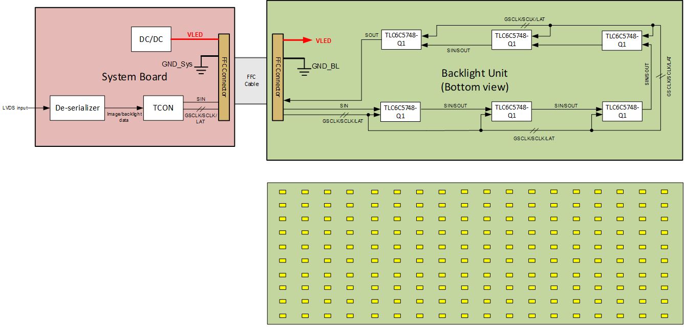
As shown in #FIG_A33_CPT_DWB, a typical local dimming system consists of a system board and an LED board.
 Figure 1-1 Typical Local Dimming System
The system board usually has a timing-controller (TCON) and some power supply circuits. The TCON accepts the image data stream for display, as well as calculating and outputting the brightness data for each backlight zone. The LED board usually has the LED matrix and the LED drivers. Connections between system board and LED board are off-board using FFC cables.
From EMC design perspective, this architecture results in below challenges,
- High frequency interface with off-board connection,
- High frequency signal routing on two-layer LED board,
Power integrity and signal integrity on LED board.