SLVAFJ1 February 2023 TPS2121
3.1 Seamless Switchover from Main Power (IN1) to Backup Power (IN2)
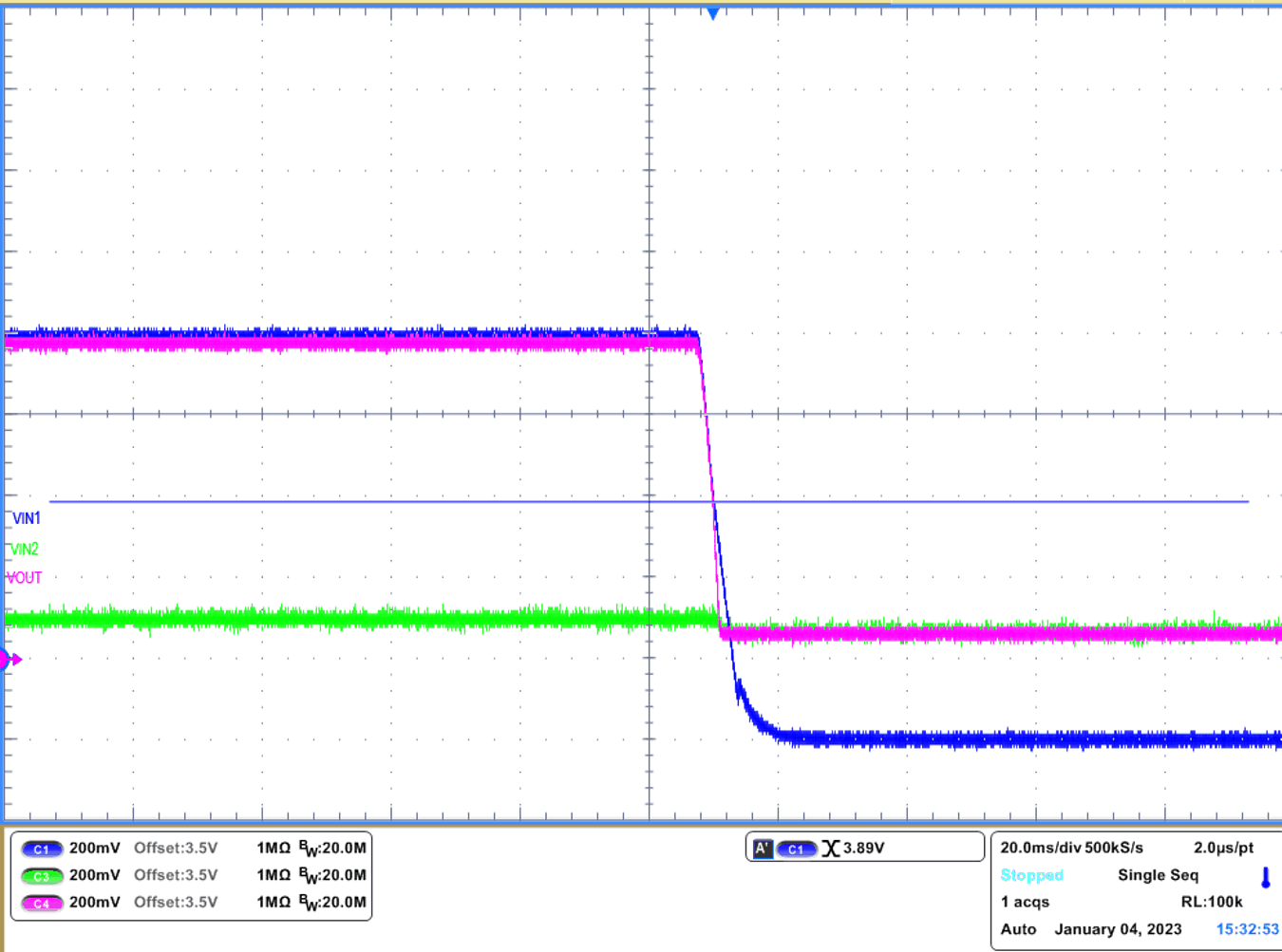
The first scenario showcases when main power source (IN1) is decreased to backup power source (IN2), resulting in automatic switchover to IN2. This design example will start automatic switchover when the voltage on IN1 is approximately 3.89 V. Since IN2 is 3.6 V, once IN1 reaches (3.6 V + VCOMP), TPS2121 will switch over to IN2. Looking at the #GUID-53F49ECD-83B0-4D52-B739-D5D20BA7CCF9, IN1 is blue line, IN2 is green line, VOUT is purple line.
 Figure 3-1 Seamless Switchover from IN1 to IN2
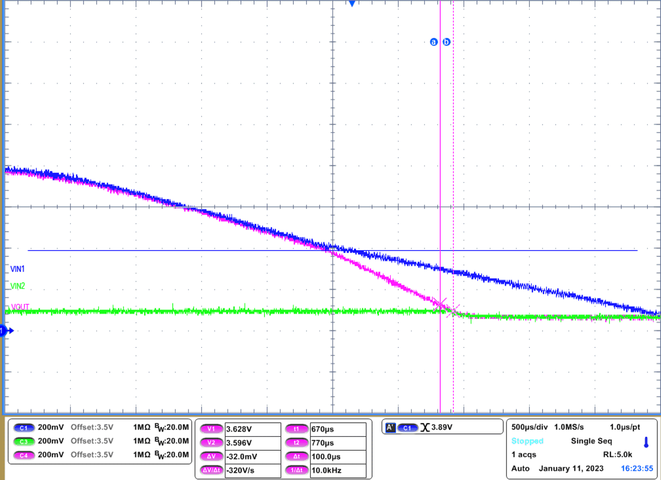
Zooming in on #GUID-90585452-4F14-431B-A8A1-B63A62CB80AD as IN1 decreases below 3.89 V, VOUT drops. Fast reverse current blocking will prevent the reverse current while VOUT is above VIN2. As the VOUT falls within VRCB of VIN2 (25 mV + 3.6 V), VIN2 quickly turns back on to avoid unnecessary voltage drops during switchover. Since expected voltage drop is 31.25 mV during switchover, VOUT drops to approximately 3.596 V. GUID-CEB450AD-E0B9-4DEA-A0E2-09452FE51AC4.html#GUID-7259EA84-6E81-41C0-AD1D-594914A8FCC1 shows this.
 Figure 3-2 Seamless Switchover from IN1 to IN2