SLVAFK5A December 2023 – February 2024 LM5177 , LM51770
4.2 Inductor Current
Figure 4-3 through Figure 4-10 shows the inductor current for different converter topologies at 2 A and 10 A load currents. The inductor current shown in all figures verifies the accurate load sharing and phase shift of 180 degrees among two parallel phases. A small error in the inductor peak current can be seen through the scope plots. This error is caused by the slight variation in the selected inductor values. The measured inductor value for phase 1 and phase 2 is 3.631 µH and 3.654 µH, respectively. Therefore, it is recommended to use the same inductor value with similar tolerance for the parallel operation. Also, in all input voltage conditions, no prominent ripple is seen in the output voltage of the parallel operation. Thus, it confirms the quality of output voltage regulation of LM5177 converters in a parallel fashion.
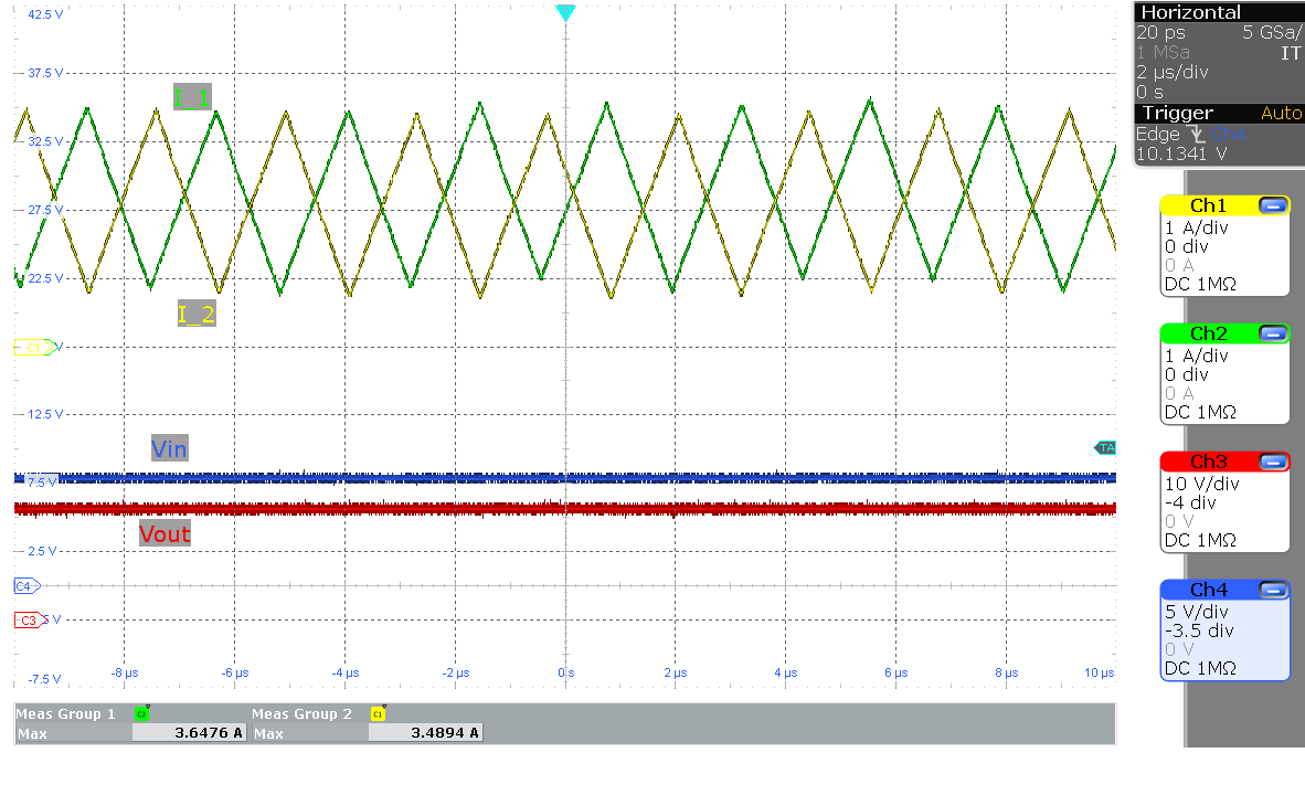 Figure 4-3 Inductor Current in Boost
Region (VIN=8 V and 2 A Load)
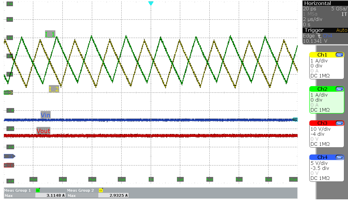 Figure 4-5 Inductor Current in Boost
Region (VIN=10 V and 2 A Load)
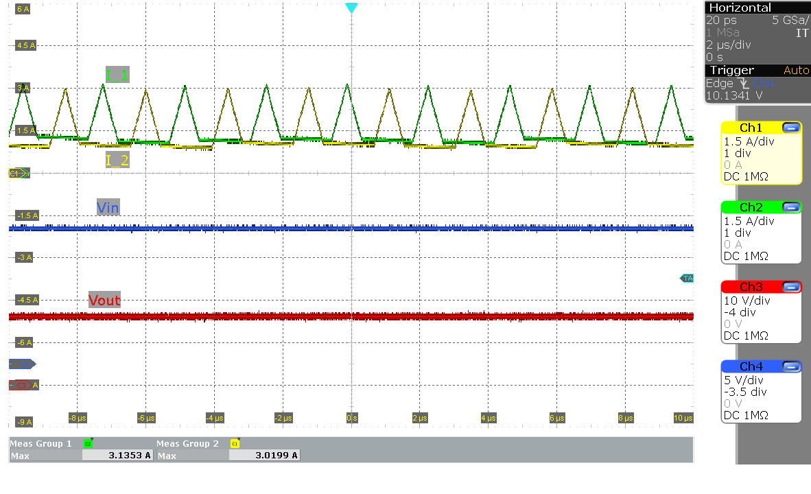 Figure 4-7 Inductor Current in
Buck-Boost Region (VIN=16 V and 2 A Load)
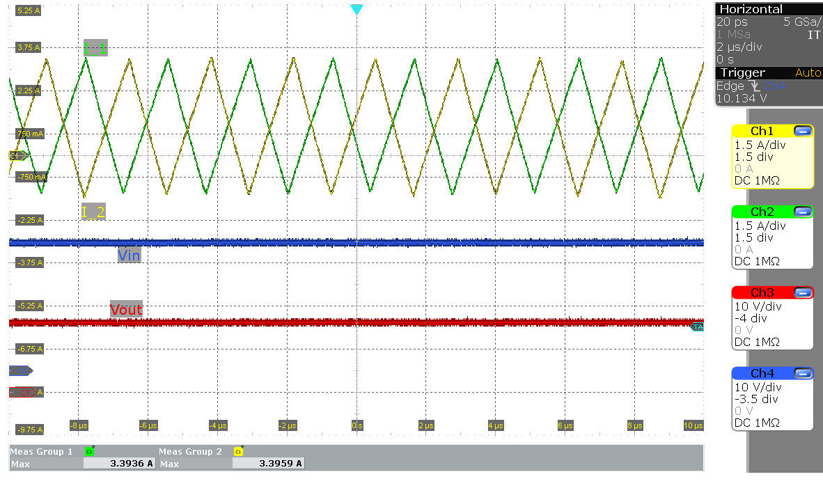 Figure 4-9 Inductor Current in Buck
Region (VIN=30 V and 2 A Load)
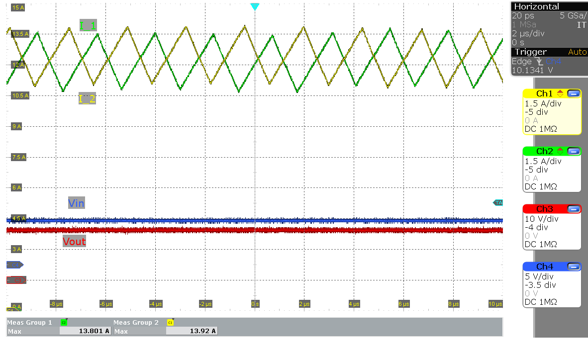 Figure 4-4 Inductor Current in Boost
Region (VIN=8 V and 10 A Load)
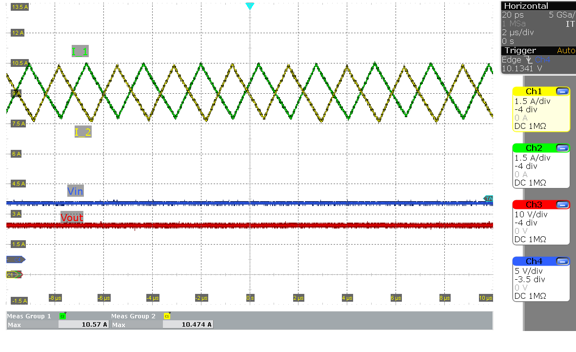 Figure 4-6 Inductor Current in Boost
Region (VIN=10 V and 10 A Load)
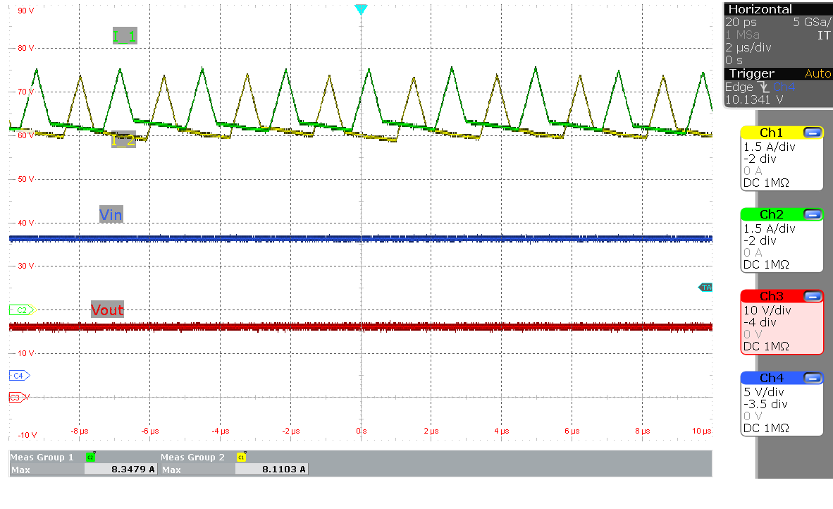 Figure 4-8 Inductor Current in
Buck-Boost Region (VIN=16 V and 10 A Load)
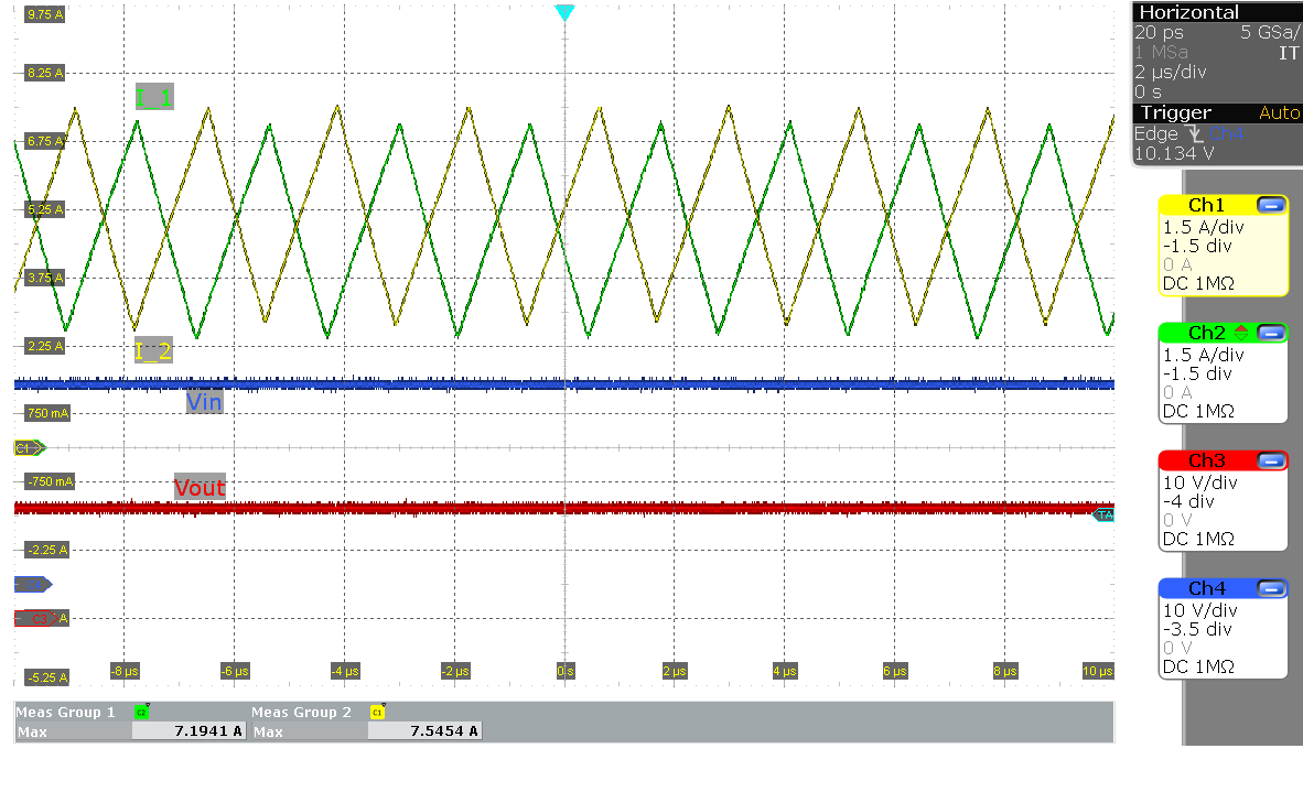 Figure 4-10 Inductor Current in Buck
Region (VIN=30 V and 10 A Load)