SLVK086A january 2022 – may 2023 TPS7H4003-SEP
PRODUCTION DATA
- 1
- Single-Event Effects Test Report of the TPS7H4003-SEP Synchronous Step-Down Converter
- Trademarks
- 1 Introduction
- 2 Single-Event Effects (SEE)
- 3 Device and Test Board Information
- 4 Irradiation Facility and Setup
- 5 Depth, Range, and LETEFF Calculation
- 6 Test Setup and Procedures
- 7 Destructive Single-Event Effects (DSEE)
- 8 Single-Event Transients (SET)
- 9 Event Rate Calculations
- 10Summary
- A Appendix: Total Ionizing Dose From SEE Experiments
- B Appendix: References
- C Revision History
4 Irradiation Facility and Setup
The heavy-ion species used for the SEE studies on this product were provided and delivered by the TAMU Cyclotron Radiation Effects Facility using a superconducting cyclotron and an advanced electron cyclotron resonance (ECR) ion source. At the fluxes used, ion beams had good flux stability and high irradiation uniformity over a 1-in diameter circular cross-sectional area for the in-air station. Uniformity is achieved by magnetic defocusing. The flux of the beam is regulated over a broad range spanning several orders of magnitude. For the bulk of these studies, ion flux of 105 ions/cm2·s were used to provide heavy-ion fluence of ≈107 ions/cm2.
For the experiments conducted on this report, Silver, 109Ag, ions at angle of incidence of 0° for an LETEFF of 48.2 MeV·cm2/mg were used. The total kinetic energy of 109Ag in the vacuum is 1.634 GeV (15 MeV/nucleon). Ion uniformity for these experiments was between 94% and 97%.
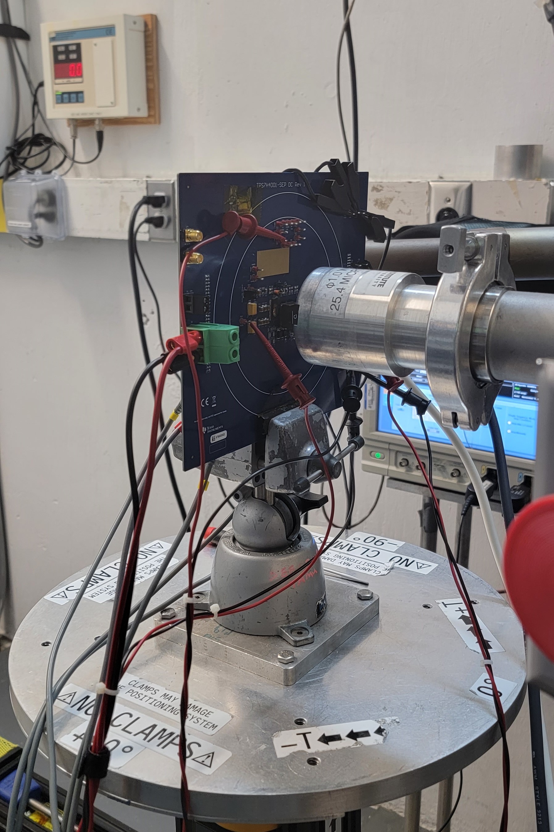
Figure 4-1 shows the TPS7H4003-SEP test board used for the experiments at the TAMU facility. Although not visible in this photo, the beam port has a 1-mil Aramica window to allow in-air testing while maintaining the vacuum within the accelerator with only minor ion energy loss. All trough-hole test points were soldered backwards for easy access of the signals while having enough room to change the angle of incidence and maintaining the 40-mm distance to the die. The in-air gap between the device and the ion beam port window was maintained at 40 mm for all runs.
 Figure 4-1 Photograph of the
TPS7H4003-SEP Daughter Card Mounted in Front of the Heavy-Ion Beam Exit Port at
the Texas A&M Cyclotron