SLVU957A September 2019 – November 2021 BQ76922
- Trademarks
- 1Features
- 2BQ76922EVM Quick Start Guide
- 3Interface Adapter
- 4Battery Management Studio Software
- 5BQ76922EVM Circuit Module Use
- 6BQ76922EVM Circuit Module Physical Construction
- 7Related Documents from Texas Instruments
- 8Revision History
4.7 Calibration
The calibration tool may not be available for all versions of devices. When the calibration tool is not available calibration of the device can be performed by entering values in the calibration section of the data memory.
The calibration writes to the volatile registers in the device which are available in the Data Memory view. When calibration values are complete they can be written to the OTP with other configuration settings. Calibration cannot be written to OTP separately from configuration settings.
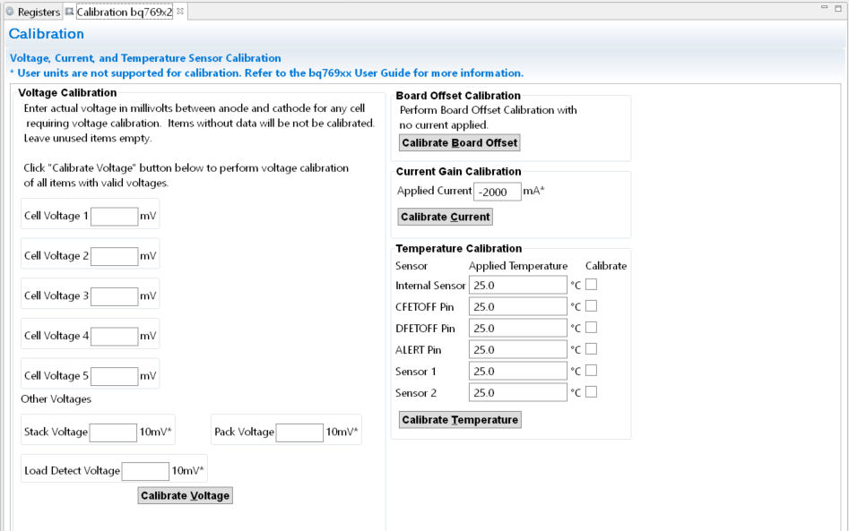
The EVM and all new boards should be calibrated before operation. The calibration view is shown in Figure 4-8. Temperature is typically calibrated first. Board Offset should be calibrated with no current flow and should be calibrated before Current Gain. The EVM uses a 1-mΩ sense resistor and calibration at low current results in some granularity from the current resolution. This may result in an apparent error at higher currents. Calibration at higher currents reduces this effect and should be done where it is important.
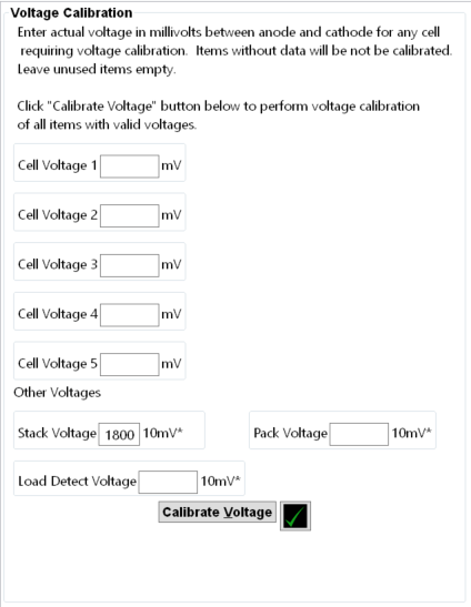
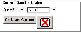
Voltages and temperatures may be calibrated individually or as a group. All values entered are calibrated. If individual values are to be calibrated, leave all the other entries blank. As an example, measure the battery voltage, calculate the average cell value and enter the value in the box. Clicking the Calibrate Voltage button runs the calibration. Values left blank or entered as '0' are not calibrated. When successful, a green check appears next to the button as shown in Figure 4-9. If there is an error, a red X appears instead as shown in Figure 4-10 with a message in the bottom border.
When calibrating the EVM voltage, remember the EVM uses 1% values for the cell simulator resistors. Measuring each cell voltage value is recommended rather than using a common value if individual cell voltage calibration is desired.
 Figure 4-8 Calibration View
 Figure 4-9 Example
Voltage Calibration Success
 Figure 4-10 Example Current Calibration Failure