SLVUBX1 December 2020 TPS63810
4.1 Buck-Boost Converter
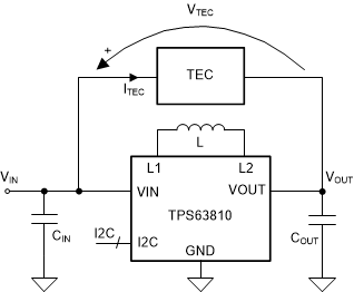
The TPS63810 is a buck-boost converter with an I2C interface. The ability of the buck-boost converter to increase or decrease the input voltage can be used to drive a TEC with positive or negative voltage. In this way, the heat flow through the TEC can be controlled in order to heat or cool the target device. Figure 4-1 shows how the TEC can be driven using the buck-boost converter. When the converter operates in buck mode, VOUT is lower than VIN, and VTEC and ITEC are therefore positive. It should be noted that in this mode, ITEC flows from VIN into VOUT pin of the TPS63810, therefore the TPS63810 output is sinking the TEC current. When the converter operates in boost mode, VOUT is higher than VIN, and VTEC and ITEC are therefore negative. It should be noted that in this mode, ITEC flows from VOUT pin of the TPS63810 back to the power source VIN, therefore the TPS63810 output is sourcing the TEC current.
 Figure 4-1 Buck-Boost Converter as TEC
Driver
Figure 4-1 Buck-Boost Converter as TEC
DriverWith the TPS63810, the TEC voltage can be easily changed via I2C interface. This reduces the component count when compared to conventional voltage scaling approaches, where a dedicated DAC or a PWM signal with associated filters and scaling resistors is used.