SLVUBX5C December   2022  – August 2024 TPS25762-Q1 , TPS25763-Q1 , TPS25772-Q1


  1.   1
  2.   Abstract
  3.   Trademarks
  4. 1Introduction
  5. 2Getting Started
    1. 2.1 Related Documents
    2. 2.2 Hardware
    3. 2.3 Software
    4. 2.4 GUI Installation and Launch
  6. 3Application Configuration Overview
    1. 3.1 Creating a New Application Configuration
    2. 3.2 Loading a Saved Configuration
  7. 4Configuration Parameters
    1. 4.1 System Power
      1. 4.1.1 System Power Management (SPM)
    2. 4.2 Internal & External DCDC
    3. 4.3 VIN Engine On or Off
    4. 4.4 Thermal Foldback
    5. 4.5 USB PORT(S)
    6. 4.6 GPIO Configuration
    7. 4.7 I2C Configuration
    8. 4.8 Device IDs
    9. 4.9 DisplayPort Alt Mode
  8. 5Application Configuration Download
    1. 5.1 Firmware Download Procedure
      1. 5.1.1 Key Upload and Binary File Generation
        1. 5.1.1.1 Firmware Update: USB Endpoint
        2. 5.1.1.2 Firmware Update: I2C
    2. 5.2 Secure Firmware Update
    3. 5.3 Optional USB Driver Installation
    4. 5.4 Direct EEPROM Programming
    5. 5.5 SSH Key Generation
  9. 6Telemetry
  10.   A TPS257XX-Q1 GUI Feature - CUSTOM ID (Version Control)
  11.   B VIN Engine On or Off (TPS257xC-Q1)
  12.   Revision History

VIN Engine On or Off

VIN Engine On or Off power level parameters are configurable in this page.

The TPS2576x-Q1 and TPS257x-Q1 family's SPM supports autonomous power transition dependent upon the VIN (for example, VBATT) voltage level per the diagram shown in Figure 4-2.
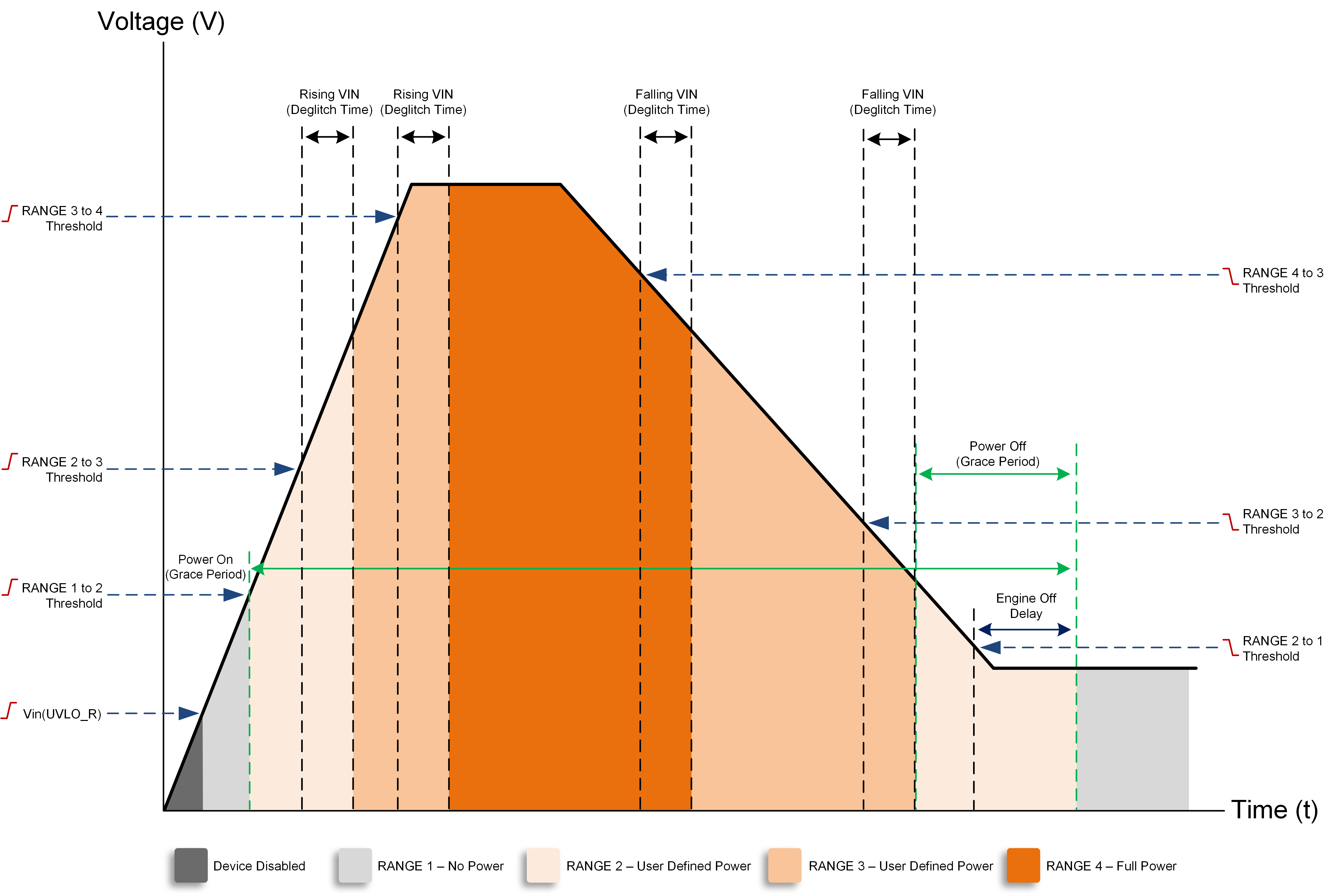
TPS25761 TPS25762 TPS25763 TPS25764 TPS25772 Engine On/Off Controls and
                    Power Mode Operation (TPS257xxD-Q1) Figure 4-2 Engine On/Off Controls and Power Mode Operation (TPS257xxD-Q1)
Note: Figure 4-2 shows the VIN Engine On/Off VIN threshold and timer parameters of TPS257xxD-Q1 devices. The naming convention of the TPS257x2C-Q1 devices' VIN Engine On/Off parameters have changed moving from GUI v1.4.0 to v2.1.0 (see Appendix B).

The Engine On/Off voltage thresholds must be configured in sequential order (highest to lowest): RANGE 3 to 4 (rising) > RANGE 4 to 3 (falling) > RANGE 2 to 3 (rising) > RANGE 3 to 2 (falling) > RANGE 1 to 2 (rising) > RANGE 2 to 1 (falling).

Maximum power for the low-power range is a configurable total port power output. Program maximum power relative to total VBUS power.

Dual port example:

  • Total USB VBUS Power = 100W
  • VBUS Port A maximum power = 60W and VBUS Port B maximum power = 60W
  • VBUS Port A minimum power = 15W and VBUS Port B minimum power = 15W
  • Maximum power for low power = 30W:
    • Once the VIN level falls below the RANGE 4 to 3 (falling) setpoint, the total USB VBUS power is reduced to 30W total for all ports.

VIN Engine On or Off is one of the SPM engine's power foldback policies. For more information regarding SPM, see the TPS257xx-Q1 System Power Management.

Note: If the maximum power for low power is less than the total minimum port power (the sum of the minimum port power for ports) ports are disabled upon entry into the low-power range.