SLVUC17 August 2021 TPS7H2211-SP
3.1 Default Configuration Results
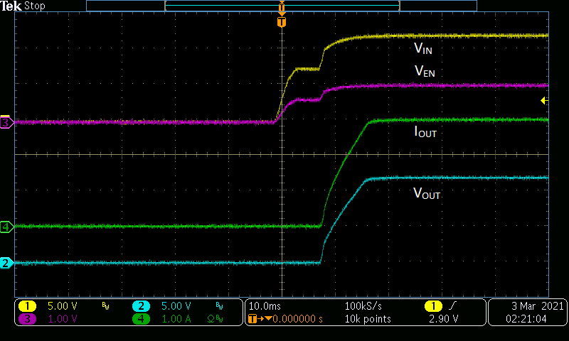
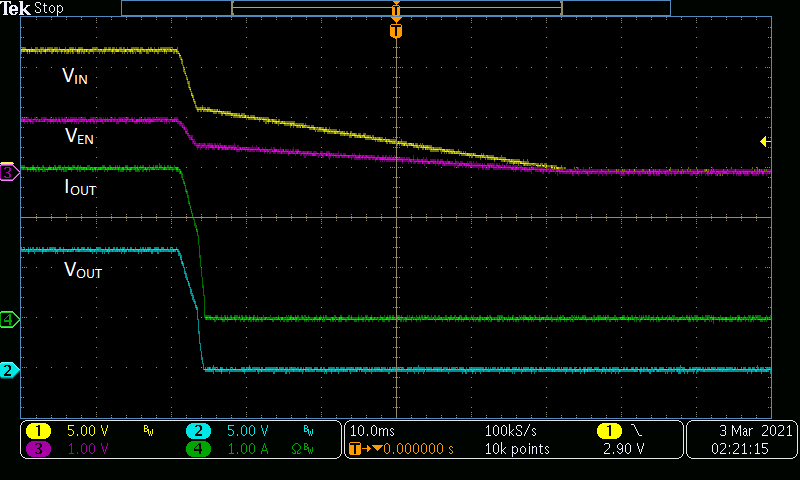
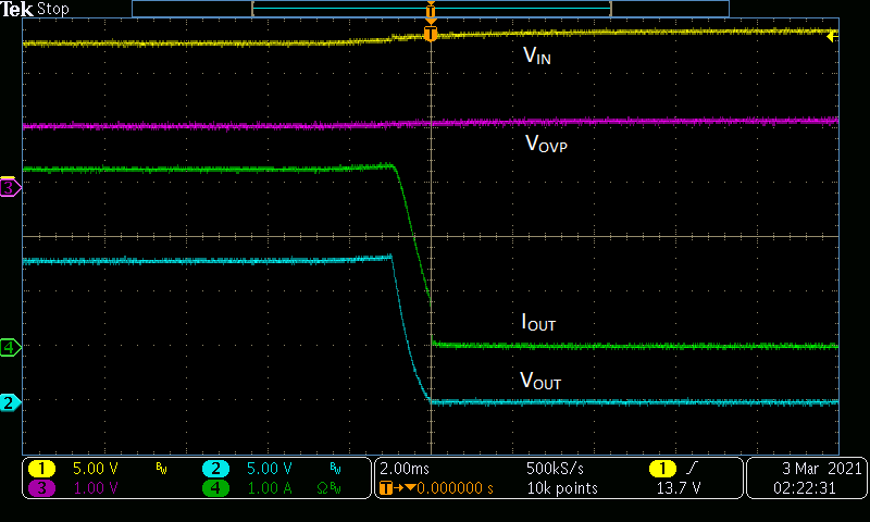
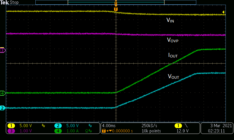
The results shown in Figure 3-1 through Figure 3-4 were observed using the TPS7H2211EVM-CVAL in its default configuration with VIN = 12 V.
 Figure 3-1 Default
Configuration: Startup
 Figure 3-2 Default
Configuration: Shutdown
 Figure 3-3 Default
Configuration: Assertion of OVP Due to Input
Voltage
 Figure 3-4 Default
Configuration: Deassertion of OVP Due to Input
Voltage