SLVUC73B January   2022  – February 2024 TPS7H4003-SEP


  1.   1
  2.   TPS7H4003EVM Evaluation Module (EVM)
  3.   Trademarks
  4. 1TPS7H4003EVM Overview
    1. 1.1 Features
    2. 1.2 Applications
  5. 2TPS7H4003EVM Default Configuration
  6. 3TPS7H4003EVM Initial Setup
  7. 4TPS7H4003EVM Testing
    1. 4.1 Output Voltage Regulation
    2. 4.2 Output Voltage Ripple
    3. 4.3 Soft Startup
    4. 4.4 Transient Response to Positive and Negative Load Step (9A to 18A to 9A)
    5. 4.5 Loop Frequency Response
    6. 4.6 Setup
  8. 5TPS7H4003EVM Schematic
  9. 6TPS7H4003EVM Bill of Materials (BOM)
  10. 7Board Layout
  11. 8Support Resources
  12. 9Revision History

Loop Frequency Response

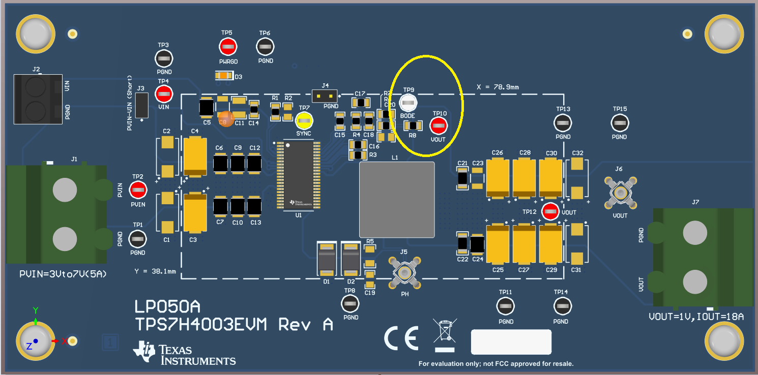
Measuring the frequency response of the feedback loop requires a unique test setup as well as physical changes to the EVM. 0Ω resistor jumper R8, below TP9 (BODE) test point and circled in yellow in the graphic below, must be lifted to break the loop. Both test points TP9 (BODE) and TP10 (VOUT) is used for connections to the Bode100 instruments.
GUID-20220114-SS0I-ZNK1-XFGB-JXBP9QCJTNQQ-low.pngFigure 4-6 EVM Modification to Measure Frequency Response