SLVUCO1A May 2023 – April 2024 DRV8213 , DRV8214 , DRV8234
PRODUCTION DATA
3.6 DRV8214EVM, DRV8215EVM, DRV8234EVM, and DRV8235EVM
The DRV8214 and DRV8234 GUI variants are identical to each other, except for some slight register map differences. The DRV8215 and DRV8235 GUI variants are also the same, but with some features disabled if the feature is not available on that device. For example, the DRV8215 device has all of the same features and controls as DRV8214 except for the RC_OUT pin and moving a set number of ripples functionality, so the controls related to those functions are disabled.
The DRV82x4/DRV82x5 GUIs have three main pages: Quick Start, Dashboard, and Register Map. The Quck Start page gives a walkthrough of how to set up the key parameters for the motor model with the device. This is intended to be followed the first time the user sets up a new motor with this device to find what register values need to be loaded for that motor. The Dashboard page provides easy access to many controls of the device on a single page including standard motor tuning, advanced tuning parameters, position control, and speed/voltage regulation control and plotting. There is also a Status & Faults and Driver Control panel that can be expanded from any GUI screen.
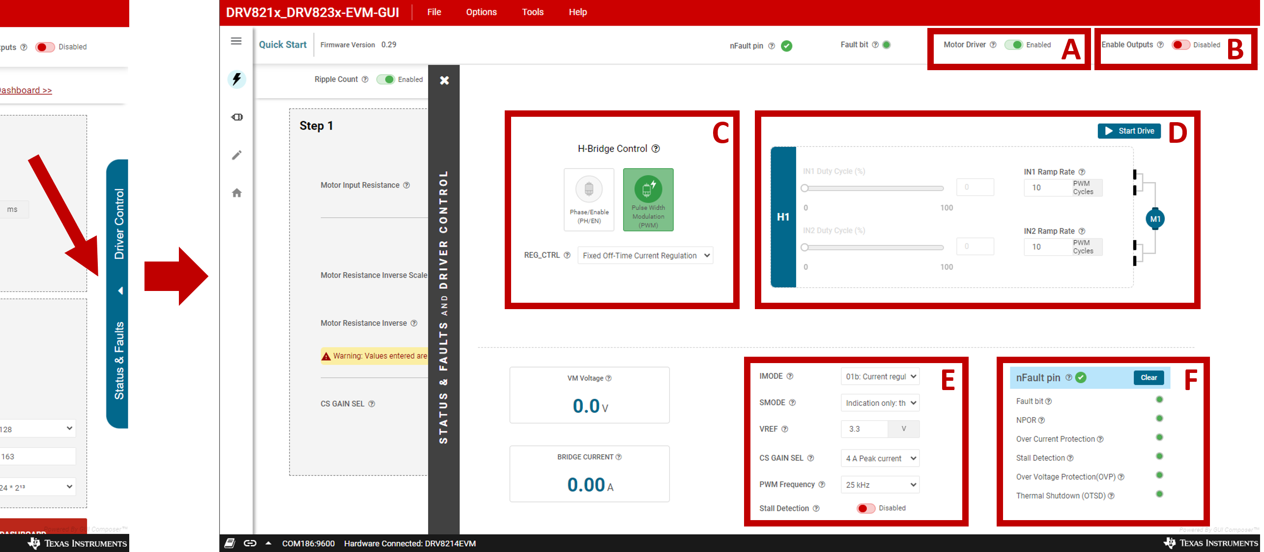
Access the Status & Faults and Driver Control pane at any time by clicking the blue control on the right side of the screen. Figure 4-7 below shows the Driver Control Panel with the main sections enclosed in red boxes with a letter assigned.
 Figure 3-7 Driver Control Panel
A: Motor Driver Enabled/Disabled
Enable/Disable motor (sets the nSLEEP pin). Set this to Enabled to activate the rest of the GUI controls.
B: Enable Outputs
Enable/Disable the motor outputs (sets the EN_OUT bit).
C: H-Bridge Control
Select between Phase/Enable (PH/EN) control mode or Pulse Width Modulation (PWM) mode. The REG_CTRL dropdown can select the current regulation mode between Fixed Off-Time, Cycle-by-Cycle, Speed Regulation, and Voltage Regualtion. These items can only be selected when the EN_OUT bit is 0, so set the Enable Outputs toggle to Disabled to modify these. See the device data sheet for more information about these modes.
D: IN1 and IN2 Control
Click Start Drive to enable the IN1 and IN2 sliders. The IN1 and IN2 duty cycle ranges from 0-100 at the user selected PWM frequency. The duty cycle is adjustable by using the slider or writing to the input box. The PWM slowly ramps up or down the duty cycle at the IN1 or IN2 ramp rate to avoid sudden speed changes. The ramp rate is adjustable from 0-25 with 0=no ramp and 25=slowest ramp rate.
The DRV8214/DRV8215 and DRV8234/DRV8235 have the capability to control the IN1 and IN2 signals via I2C. To enable this control method, set the I2C_BC bit in register CONFIG4 to 1b to enable SPI control. Then simply set the IN1 and IN2 bits in CONFIG4 register to control the motor.
E: Various Mode Controls
This section displays the firmware version, VM voltage, contains input widgets for configuring IMODE, SMODE, VREF, CS GAIN SEL (current sense gain selection), stall detection, and PWM frequency for external IN1 and IN2 signals. To change the PWM frequency, the motor has to be stopped. This can be achieved by disabling the outputs or clicking on the Stop Drive button in section B.
F: Fault Status
This section displays indicators for various fault conditions. To clear any fault, click on the Clear button.asdfvidual registers. Immediate write option writes to the registers right after modification while deferred write requires manual input to write.