SLVUCO6 june   2023 TPSI2072-Q1


  1.   1
  2.   Abstract
  3.   Trademarks
  4.   General Texas Instruments High Voltage Evaluation (TI HV EVM) User Safety Guidelines
  5. 1Introduction
    1. 1.1 Features
    2. 1.2 Applications
    3. 1.3 Description
  6. 2Connection Descriptions
  7. 3Test Equipment
  8. 4Recommended Test Setup
    1. 4.1 Waveforms
    2. 4.2 VS1_ADC and VS2_ADC Voltage Dividers
  9. 5Schematic
  10. 6PCB Layout
  11. 7Interlayer Stitching Capacitor
    1. 7.1 Interlayer Stiching Capacitors & EMI Performance Improvements
    2. 7.2 VS1_ADC and VS2_ADC Voltage Dividers
  12. 8Bill of Materials
  13. 9Revision History

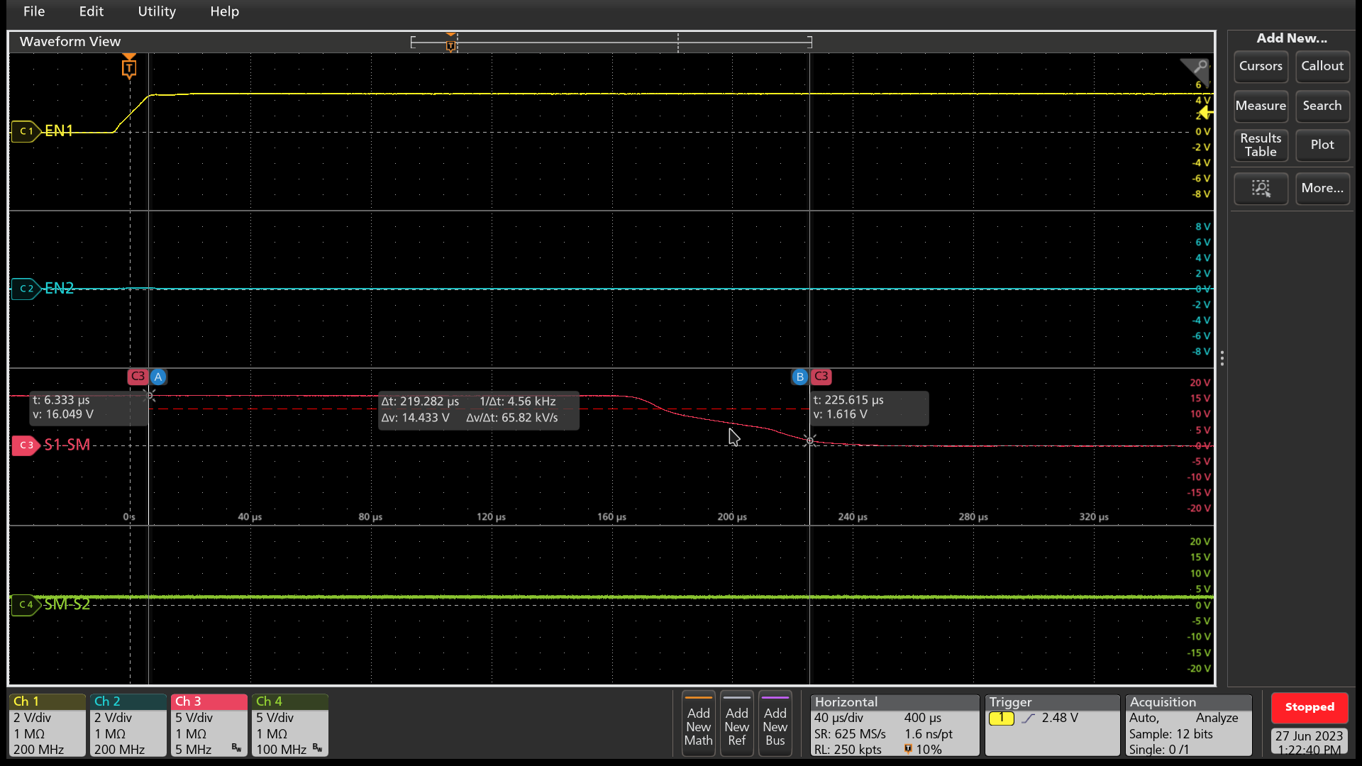
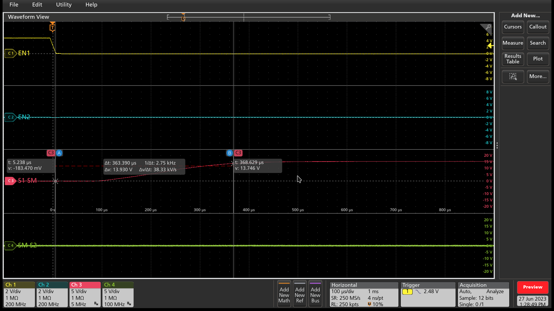
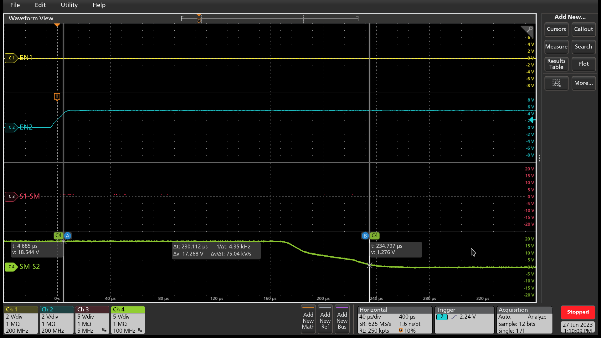
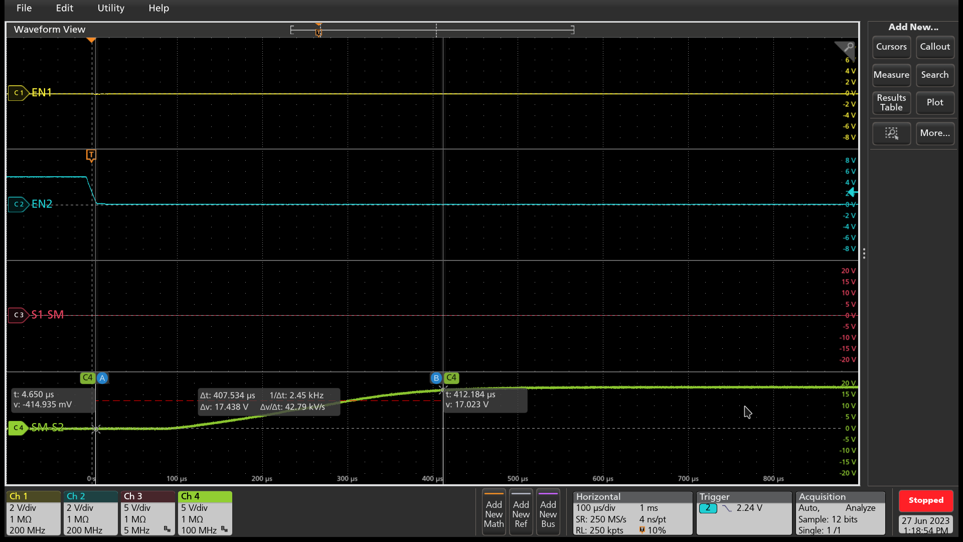
Waveforms

If connected as described above, the following channels must be displayed in the waveforms below:

  • CH 1 = EN1

  • CH 2 = EN2

  • CH 3 = S1-SM

  • CH 4 = SM-S2

GUID-20230627-SS0I-3SX3-14DX-BQPZPDVVT4TW-low.pngFigure 4-2 RN1 Rise Time

GUID-20230627-SS0I-JSJZ-MMMH-4LD4NDTFLCHJ-low.pngFigure 4-3 EN1 Fall Time

GUID-20230627-SS0I-02CD-5RRX-WRFPFZJQLCXB-low.pngFigure 4-4 EN2 Rise Time

GUID-20230627-SS0I-SFQS-VT0V-F4JBRPHDZ4WK-low.pngFigure 4-5 EN2 Fall Time