SLVUCR9B August 2023 – January 2024 TPS2HCS10-Q1
2.1 Assembly Instructions
To get started with the HSS-HCMOTHERBRDEVM the following resources are required:
- 1x HSS-HCMOTHERBRDEVM
- Firmware is pre-flashed for the EVM and no need for the user to program the EVM initially.
- Standard USB cable included.
- 1x HSS-2HCS10EVM daughter card (or any compatible high-side switch daughter card EVM).
- Windows host with .NET framework run-time
v4.7.2 (included in all Windows 10 versions).
- Can be downloaded form https://dotnet.microsoft.com/en-us/download/dotnet-framework/net472 for all other versions.
- Texas Instruments Smart Fuse Configurator software tool (4MB).
No special drivers or large proprietary frameworks are needed to run the Smart Fuse Configurator.
To get started, plug the daughter card into the headers marked J1 and J2 on the HSS-HCMOTHERBRDEVM as seen below. Note that the dots on the motherboard and daughter card signify the pin 1 connection for proper alignment.
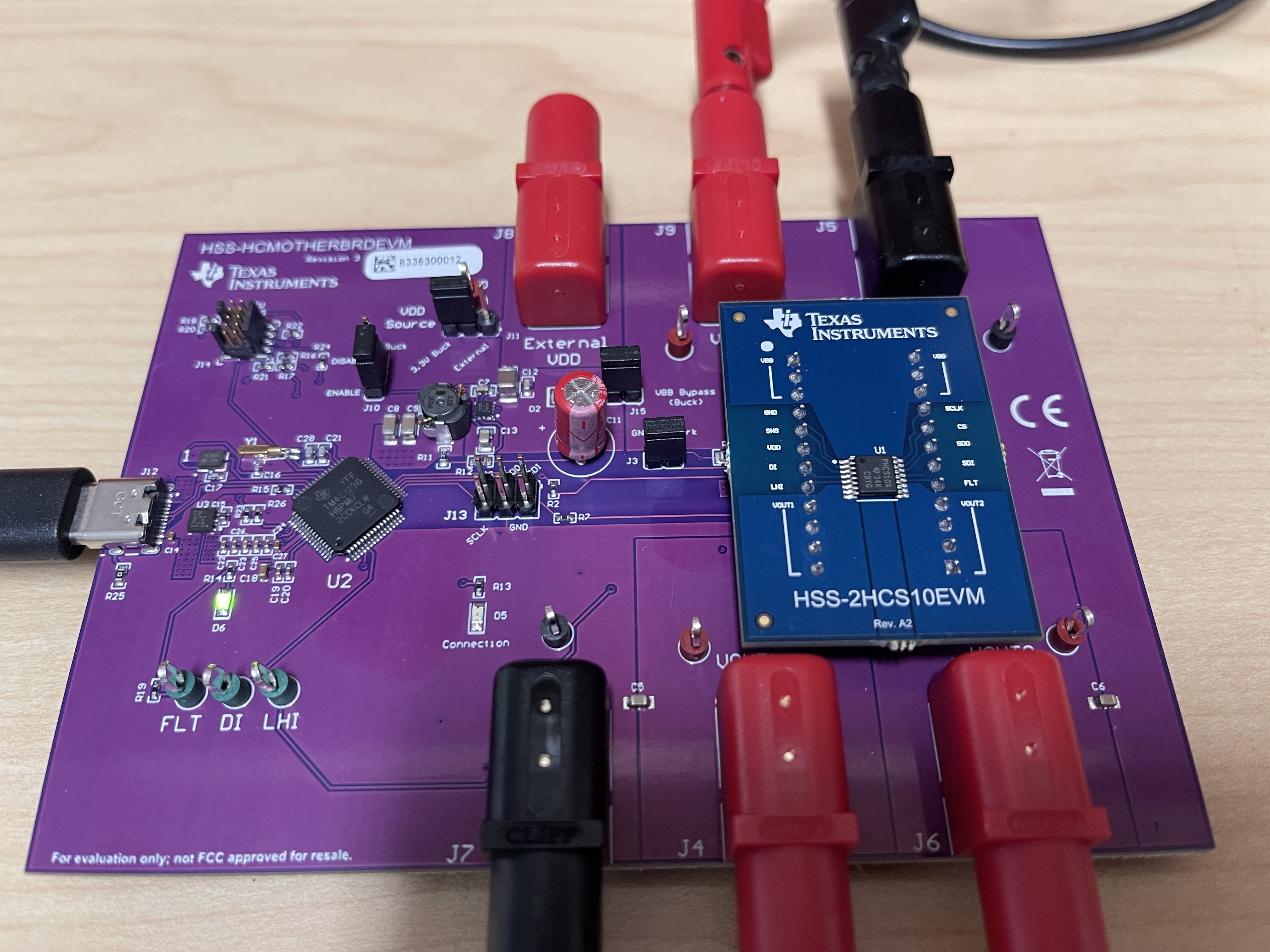 Figure 2-1 Board Alignment
Next, plug the USB-C cable into the HSS-HCMOTHERBRDEVM as seen below.
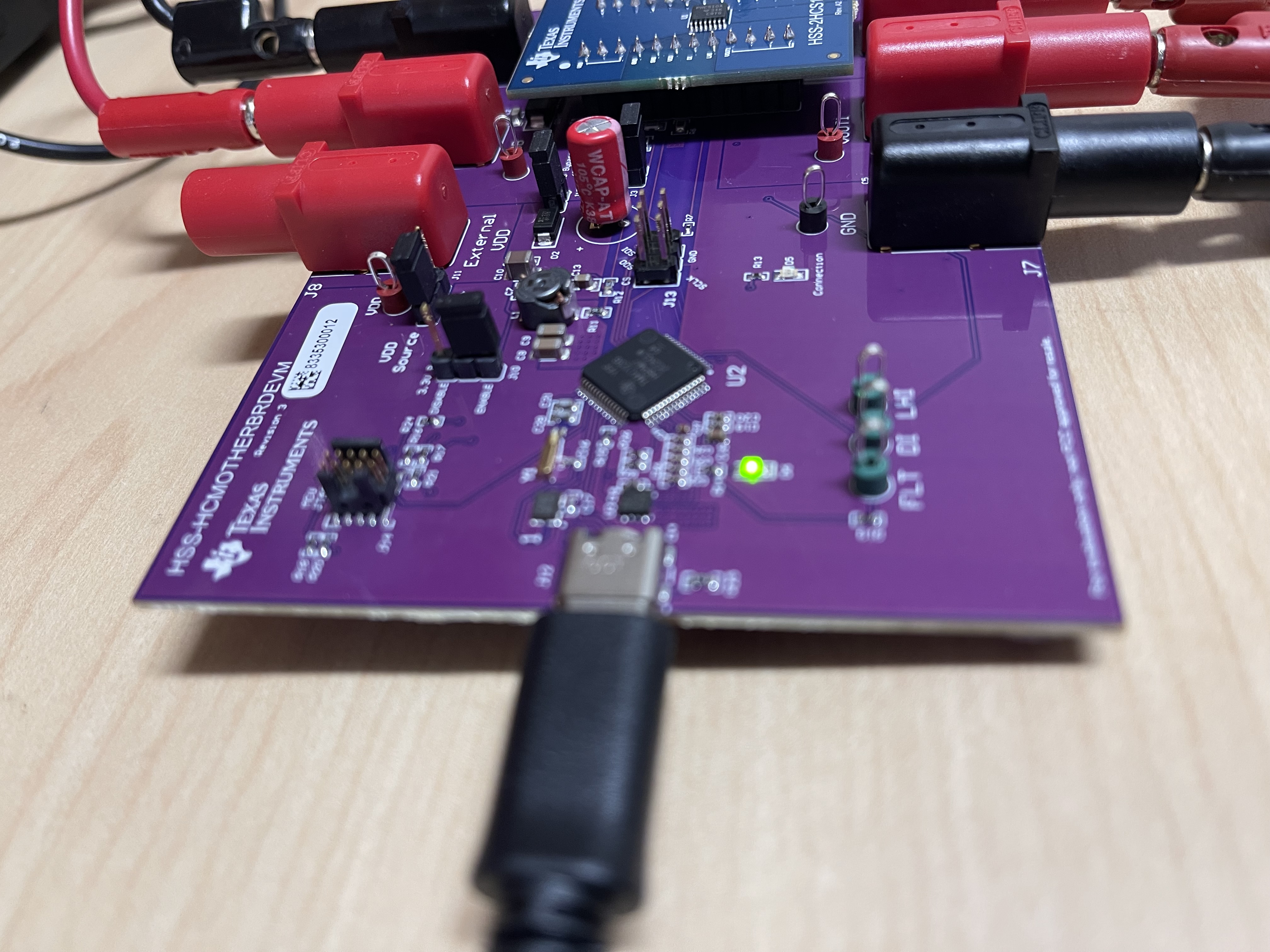 Figure 2-2 USB Connection
If successful, then the green LED on D2 illuminates and Windows automatically detects/installs the high-side switch EVM.
Next, connect the relevant power supply to the VBB banana jack (J8) and connect the ground connection of the power supply to the GND banana jack of the EVM (J7) as seen below. Do the same for the desired load connections VOUT1 (J3) and VOUT2 (J4). Make sure that the ground connections of the loads are connected back to a ground port of the EVM (such as J9).
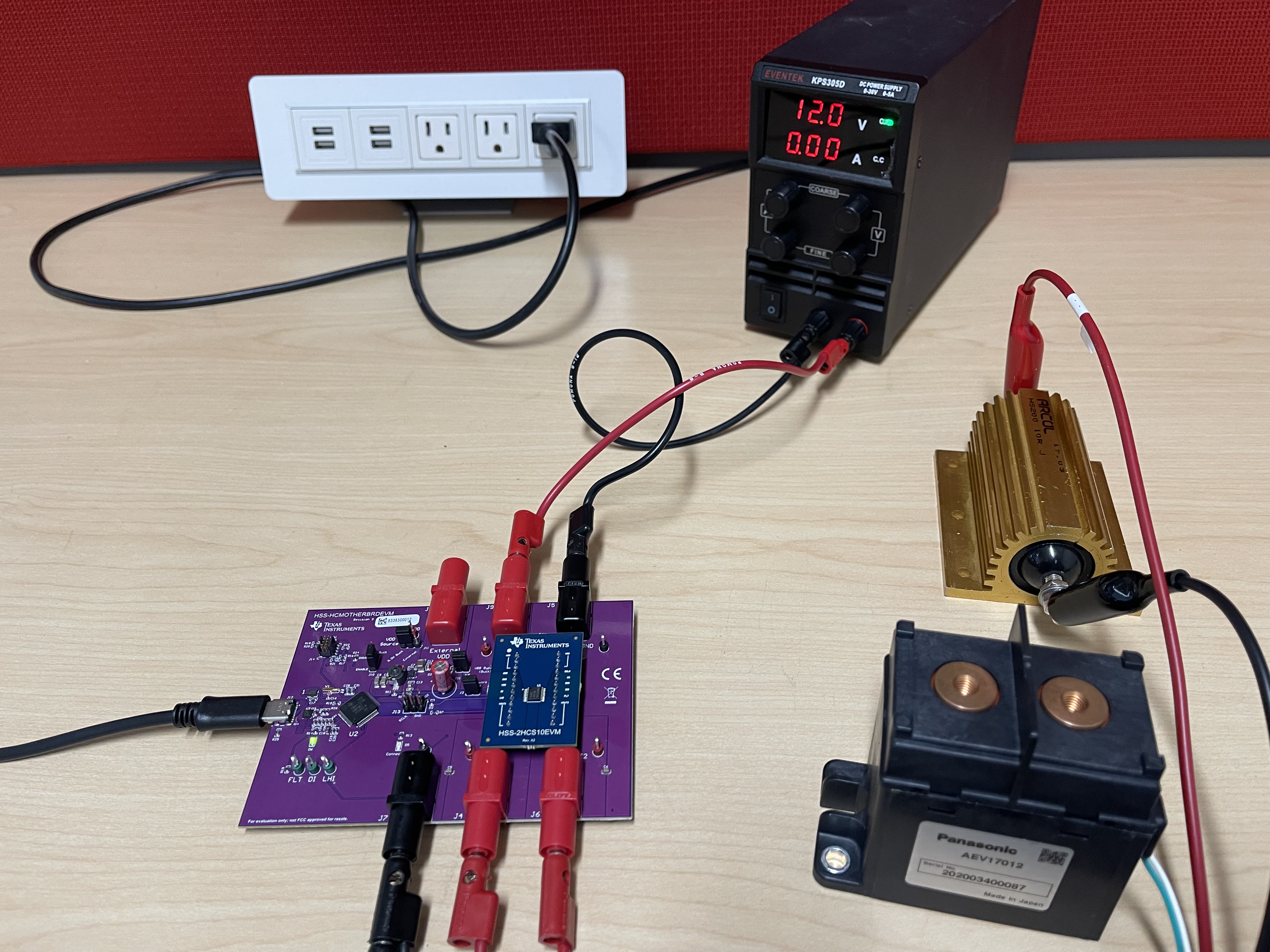 Figure 2-3 Loads Connected
With all of the supply, loads, and USB connected, turn on the power supply to the EVM. Note that the high-side switches used in this EVM are designed for 12 V automotive systems, however refer to the device data sheet for exact details on the input/output conditions supported.
With the device powered, open the auto_hss_configurator.exe executable that ships with the Smart Fuse Configurator software package. Note that the software package from TI.com is a portable zip file and does not need any specific installer to operate. Once opened, the software program automatically detects the attached high-side switch and updates the connection status to Connected as seen in the figure below:
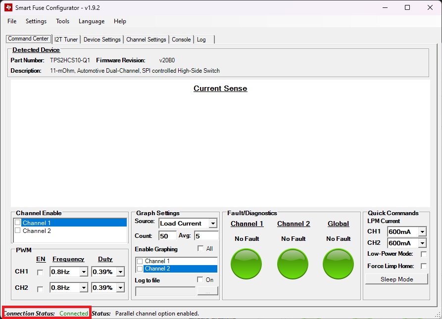 Figure 2-4 Connected
If the EVM is not connected, then the Connection Status shows up as Disconnected. In this state, the main elements of the GUI are disabled until the device is connected.
On the main interface, the status bar displays the latest command/status event that happened on the GUI. In this case, the status bar message shows that the high-side switch device was connected from the High-side switch device found and connected message. Whenever a setting is changed on the device or a significant setting is change on the GUI a message is displayed in the status bar. A timestamped list of all previous events can be seen in the Log tab as seen below.
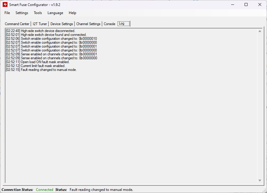 Figure 2-5 Log View
Once connected, the GUI communicates with the EVM and read out both the device ID string as well as the firmware revision from the EVM. This information is displayed under the Detected Device section in the Command Center tab.
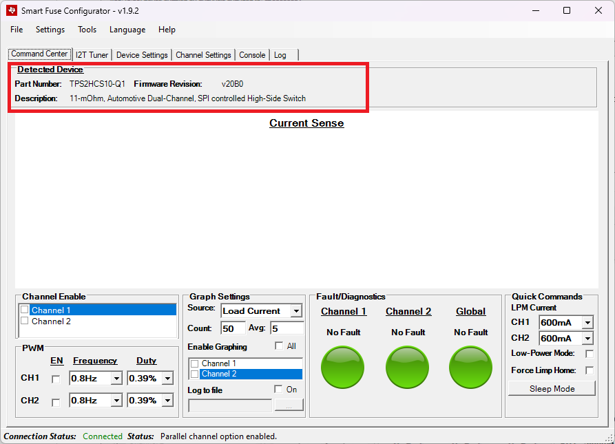 Figure 2-6 Firmware Version
The detailed usage guide for each of the tabs in the software can be found in the sections below.