SLVUCV7 April 2024 TPS23881B
- 1
- Description
- Get Started
- Features
- Applications
- 6
- 1Evaluation Module Overview
-
2Hardware
- 2.1 EVM Input/Output Connectors and Switches
- 2.2 EVM LEDs
- 2.3 EVM Test Points
- 2.4 EVM Test Jumpers
- 2.5 Quick Start
- 2.6 TPS23881B1 Autonomous Operations
- 3Software
- 4Hardware Design Files
- 5Additional Information
3.1.2 TPS23881B1EVM GUI Operation
Start the TPS23881B1EVM GUI by double-clicking the GUI icon. A window similar to Figure 4-1 comes up.
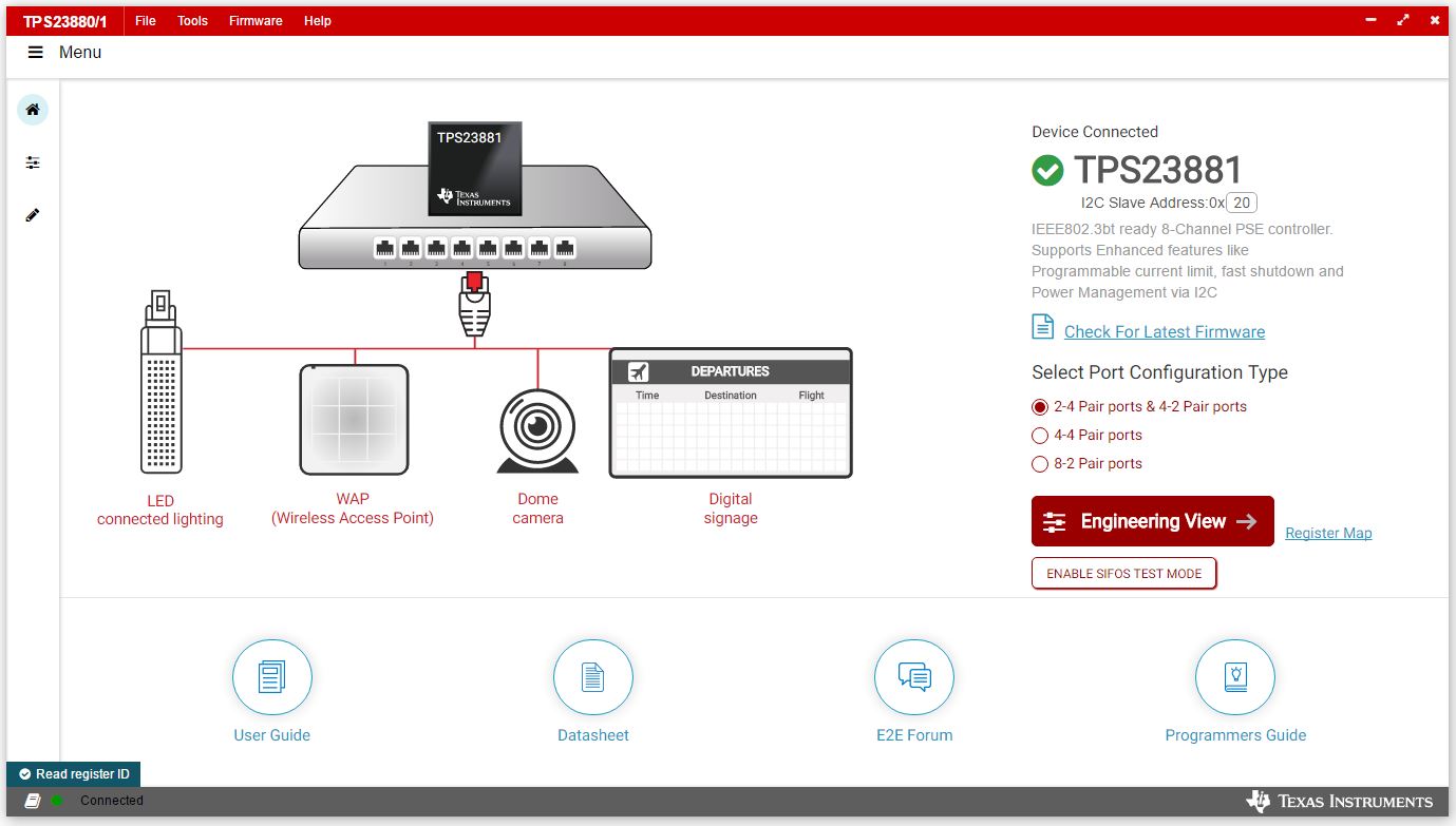 Figure 3-1 TPS23881B1EVM GUI Start-up Window
The default device address in the GUI is set to 0x20 which matches the default configuration of the EVM (J4 on the daughter card is installed with jumpers). The GUI sets the TPS23881B1 in configuration B mode (see the GENERAL MASK Register section of the data sheet for details). The address can be programed through the A1 to A4 pins and the I2C address setting in the GUI needs to match the hardware configuration. See the Pin Status Register section of the data sheet for details. The Startup page contains links to the EVM user's guide, TPS23881B1 data sheet, E2E forum and MSP430 reference code. Four popular PD end-equipment images are connected to the PSE switch. Links to the recommended PD device for each end equipment are also provided.
The TPS23881B1 is intended to be operated without loading firmware. If the user wants to load different version of firmware, then click Load Firmware and choose SRAM code as desired.
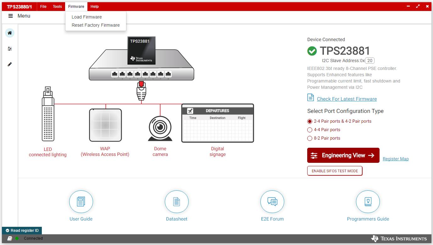 Figure 3-2 TPS23881B1EVM GUI Load
Firmware 1
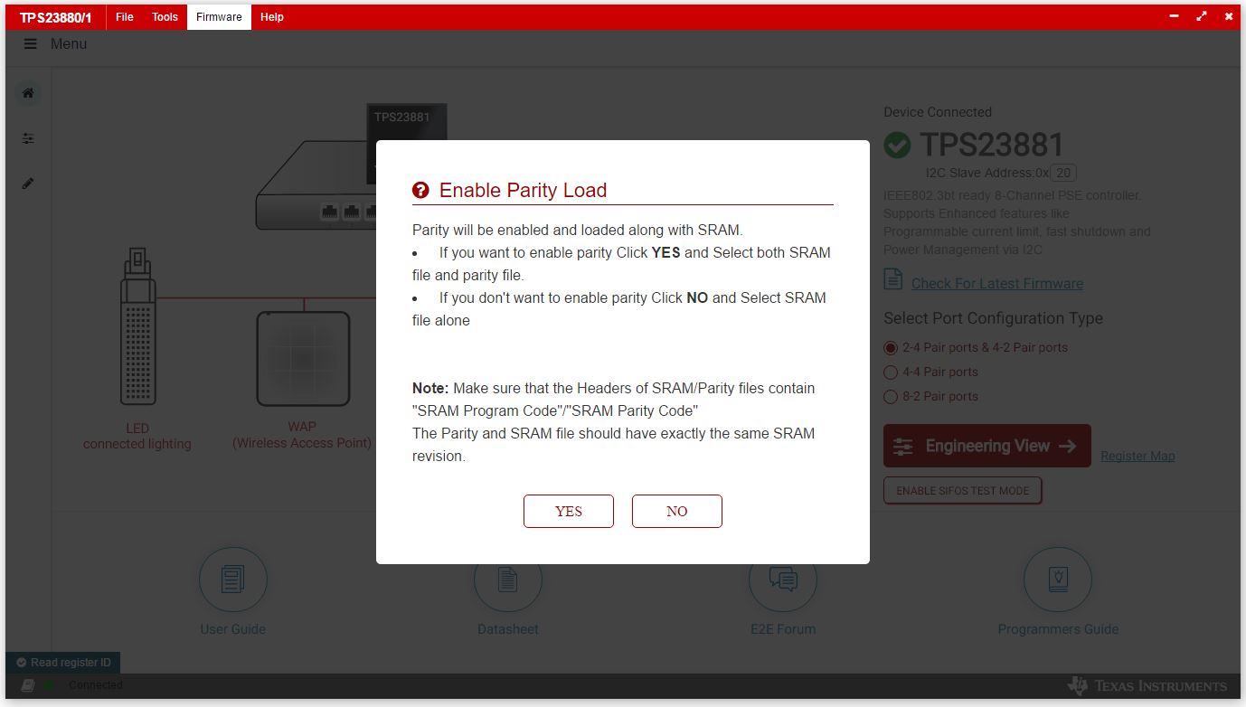 Figure 3-3 TPS23881B1EVM GUI Load
Firmware 2
Figure 3-3 TPS23881B1EVM GUI Load
Firmware 2Once firmware is successfully loaded and Device Connected displays and port configuration type is selected, click Engineering View.
On the page displayed in Figure 4-4, each port can be configured separately by clicking each RJ45 connector. By default, the TPS23881B1 is configured in OFF Mode. Each port can be configured by clicking the RJ45 icon. Clicking the SET ALL PORTS TO STANDARD button sets all port to standard configurations (configuring ports in Semi-Auto mode, enabling OSS, power policing, and DC disconnect). Clicking the SET ALL PORTS TO AUTO MODE button enables Auto Mode for all ports.
The status of each port is shown on the configuration and telemetry page. The configuration of the ports can also be edited on this page by clicking the RJ45 connector.
If the port is configured in Auto Mode, then the port turns on automatically by the PSE device after connecting a valid PD. If not configured in Auto Mode, then a port enable command is required (4P Enable for 4 pair ports and 2P Enable for 2-pair ports). The port can be turned on only when the PD has valid detection and classification results.
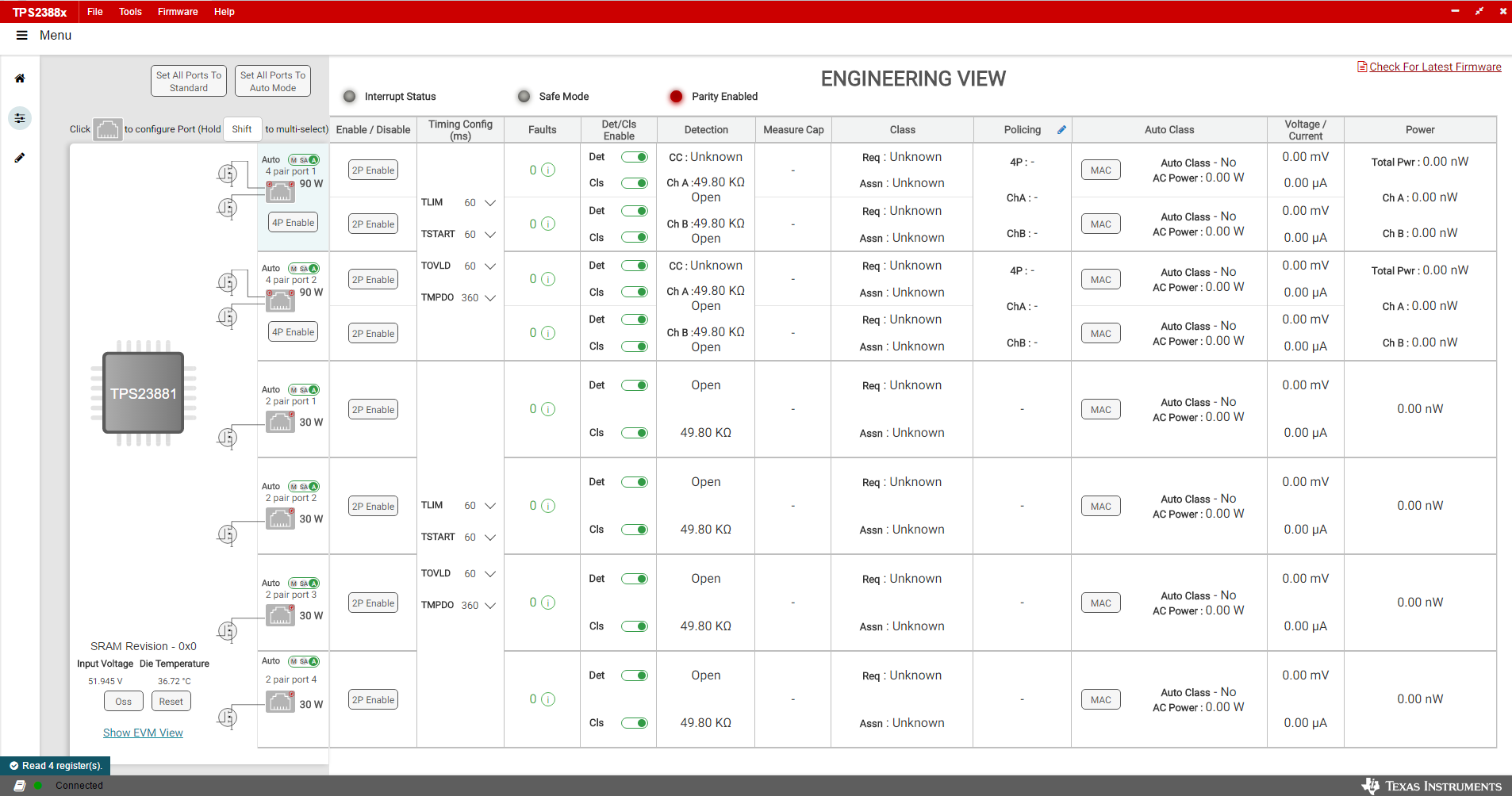 Figure 3-4 Device
Configuration and Port Telemetry Page
Figure 3-4 Device
Configuration and Port Telemetry PageThe GUI also provides access to every register of the device in the register map.
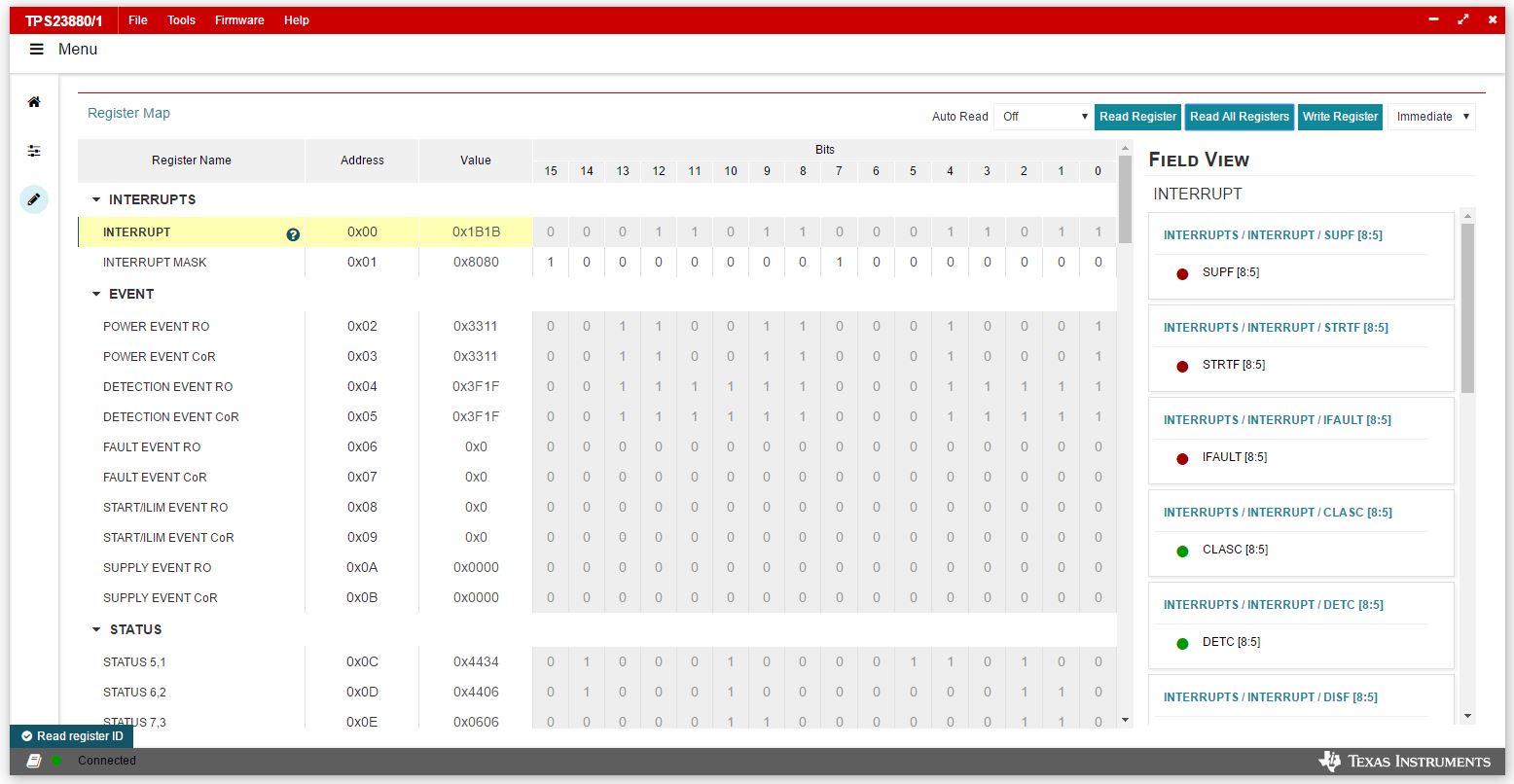 Figure 3-5 Register
Map